|
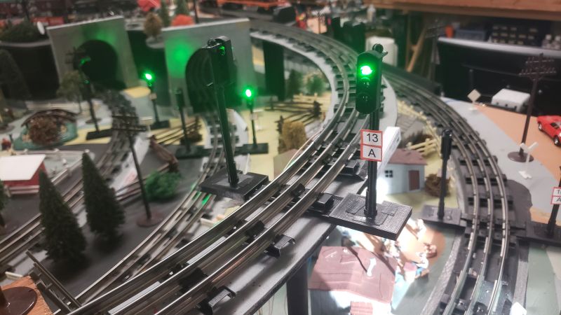
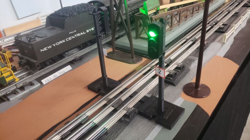
Here is the script CheckSignals Test.lua.
--[[
---------------------------------------------------------------------------
Remote Train Control Program for Windows

© Copyright 2026 by Mark DiVecchio

	This file is part of Remote Train Control.

	Remote Train Control is free software: you can redistribute it and/or modify
	it under the terms of the GNU General Public License as published by
	the Free Software Foundation, either version 3 of the License, or
	(at your option) any later version.

	Remote Train Control is distributed in the hope that it will be useful,
	but WITHOUT ANY WARRANTY; without even the implied warranty of
	MERCHANTABILITY or FITNESS FOR A PARTICULAR PURPOSE.  See the
	GNU General Public License for more details.

	You should have received a copy of the GNU General Public License
	along with Remote Train Control.  If not, see <http://www.gnu.org/licenses/>.

 Home Page : http://www.silogic.com/trains/RTC_Running.html
---------------------------------------------------------------------------]]
-- Semicolons are not required in Lua code
title = "Check Signals Test"
require([[defines]]);
require([[functions]]);
--
-- flashes green/yellow/red on all available signals
--
local Layout = nil;

--[[---------------------------------------------------------------------------------------]]
function setup(Engine, TIU)
	print("setup() Running");

	-- Instrumented Layout 4
	Layout = require([[Layout4]]);		-- All of the details about the Layout

	ShowLayout();		-- SetAspect() requires that a layout window be open

	local NumSignals;
	NumSignals = GetSignals();
	print("Number of Signals = " .. NumSignals);

	-- check that all signals were found
	local SignalMissing = false;
	for orig_key, orig_value in pairs(SignalNames) do
		if (type(orig_key) == "number") then
			local res = CheckSignal(orig_key);
			print("Signal #" .. orig_key .. " - " .. orig_value .. " = " .. tostring(res));
			if (res == false) then
				SignalMissing = true;
				end;
			end;
		end;

	if (SignalMissing) then
		return Stop("Did not find all signals");
		else
		print("All Signals found");
		end;

	return true;		-- false=setup failed, true=setup succeeded
	end
--[[---------------------------------------------------------------------------------------]]
function loop(Engine, TIU)
	-- Always call Sleep(X) at least once in this function if it returns true;
	print("loop() Running");

	for orig_key, orig_value in pairs(SignalNames) do
		if (type(orig_key) == "number") then
			print("Signal #" .. orig_key .. " to red - " .. orig_value);
			SetAspect(orig_key, AsStopSignal);
			Sleep(1);
			end
		end

	for orig_key, orig_value in pairs(SignalNames) do
		if (type(orig_key) == "number") then
			print("Signal #" .. orig_key .. " to yellow - " .. orig_value);
			SetAspect(orig_key, AsApproach);
			Sleep(1);
			end
		end

	for orig_key, orig_value in pairs(SignalNames) do
		if (type(orig_key) == "number") then
			print("Signal #" .. orig_key .. " to green - " .. orig_value);
			SetAspect(orig_key, AsClear);
			Sleep(1);
			end
		end

	Sleep(10);
	return true;
	end
--[[---------------------------------------------------------------------------------------]]
function cleanup(Engine, TIU)
	-- this function is called once when the user presses the [STOP] button or the Stop() function is called
	print("cleanup() Running");
	return true;		-- false=cleanup failed, true=cleanup succeeded
	end
--[[---------------------------------------------------------------------------------------]]
|
 I
started developement of this web page in April 2026. It will be under
construction for a while.
I
started developement of this web page in April 2026. It will be under
construction for a while.
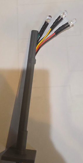
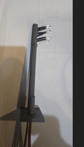
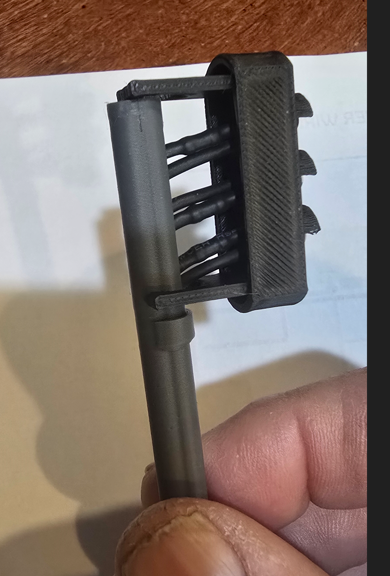
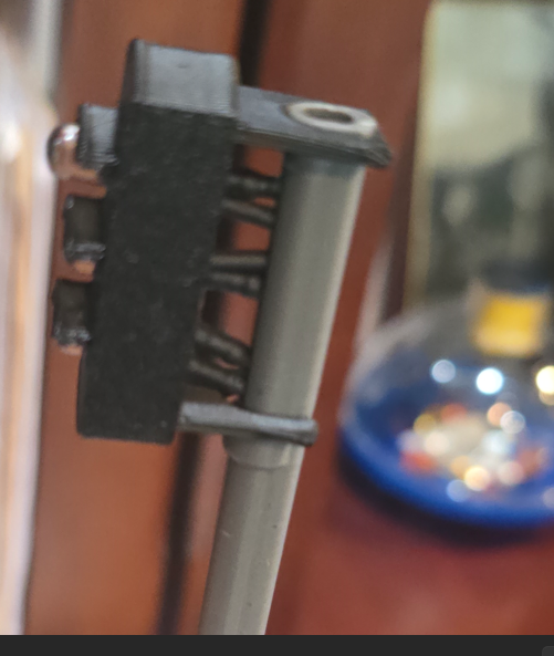
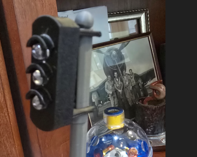
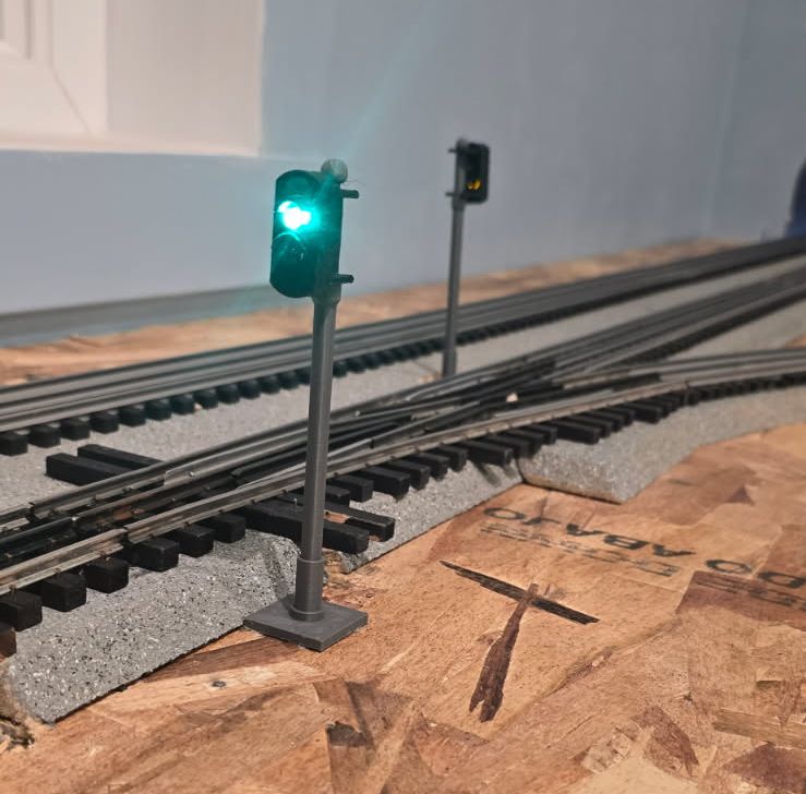


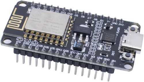
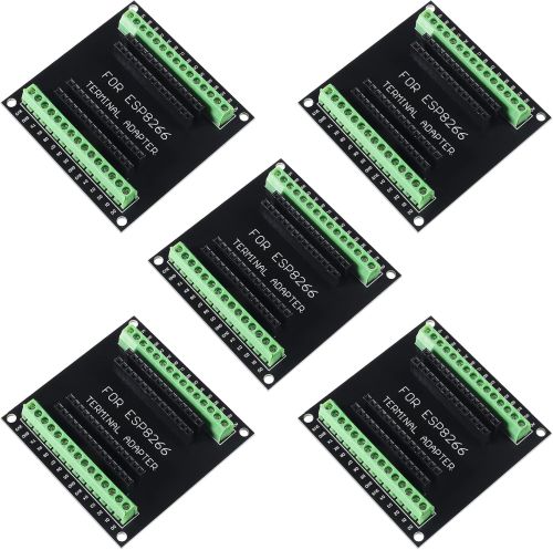
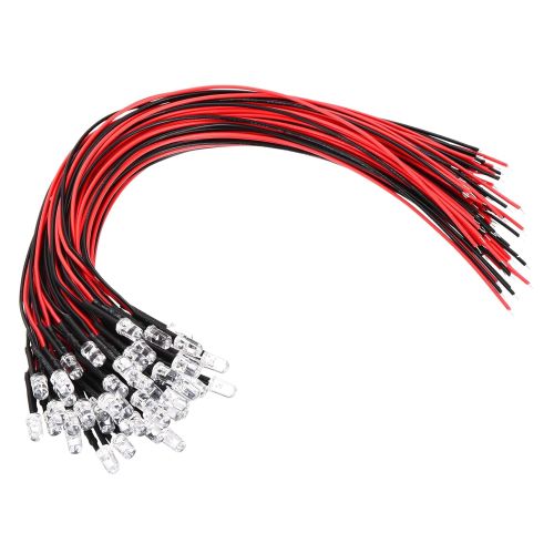
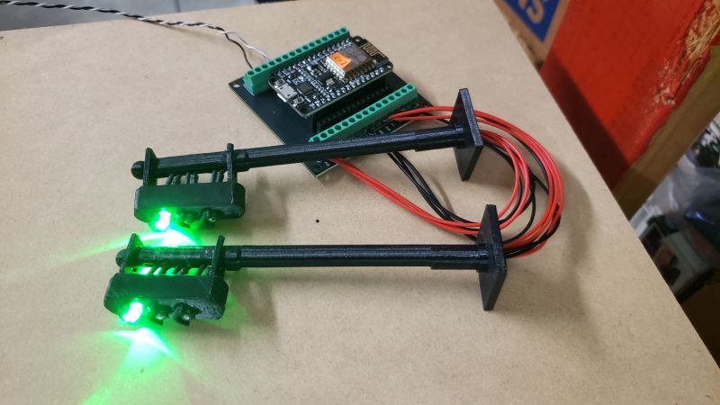
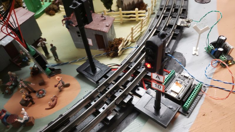
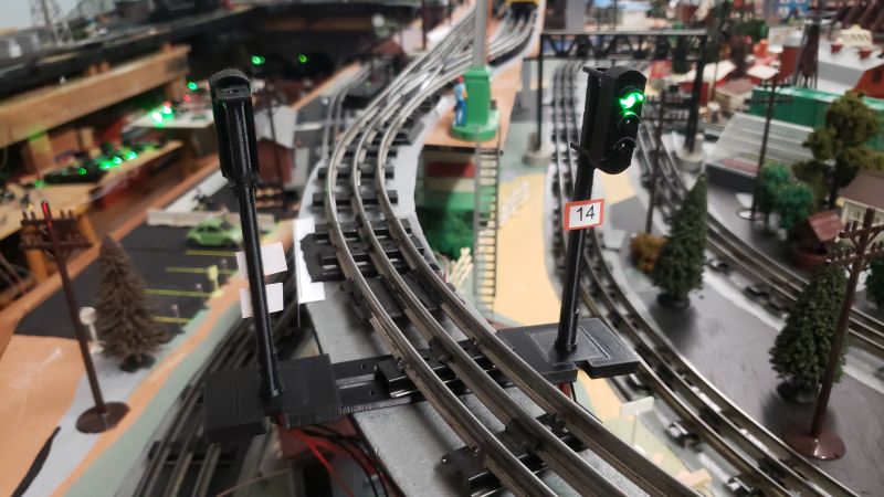
 Installing the Signals Permanently on the Layout