Mark DiVecchio's O-Gauge Train Layouts
WiFi Support
for RTC
This Page last updated on
.
 I
started developement of this web page in January 2022. It will be under
construction for a while.
I
started developement of this web page in January 2022. It will be under
construction for a while.
On this page, I describe the work that I've been doing to implement the
use of WiFi to connect to my layout. I started on the coding around
September of 2021 for my RFID Detection system. Major updates in
December of 2024 to support the new WTIU.
RTC still supports CC1101E radio control over USB so even if you don't
have a WIU or WTIU, you can still try out the other new features.
Even though I did the RFID programming first, I'll be talking about the
WTIU connection first since it is more useful to most people.
I’ve spent time examining how the MTH App works with
the WTIU and I found areas
where RTC works differently. I think it is important that RTC and the
App both handle the TIU the same way. I’ve also found things
in the
App that don’t work (esoteric modes like All Engine Operation
when
the TIU are in Super TIU mode). Of course, the user interface is
different since RTC is designed to run on a Windows based computer
not on a tiny smartphone screen.
Throughout this
document, when I say WTIU, that includes the older WIU/TIU
combination. I continue to confuse myself with this .....
Downloads
You can download v5.0 of RTC from
here.
This web page mostly refers to WiFi mode using the WTIU because that is
where the
major changes for v5.0 lie. For uses of serial RS-232 mode with a
CC1101
radio, the operation should be unchanged with the exception of the need
to select active TIU and the limit of 97 engines.
You have to setup the WIU/TIU or WTIU following MTH's instructions.
That includes connecting it to your home router over WiFi. Once you do
that, RTC should find them automagically.
I also have a support program that helps to confirm that the WiFi is
correctly connected up. You can find out about it further down this
page or you can click here.
 The Next Step -
Connecting directly from RTC program to the WIU/WTIU
The Next Step -
Connecting directly from RTC program to the WIU/WTIU
When I started my work on RTC, I used a wired interface to connect the
PC to the TIU. Later, I learned how to use a CC1101 radio
to connect directly. The radio was connected to the PC using a USB
cable. Now the ultimate(?) implementation - I can get rid of the USB
cable and Radio by using WiFi to connect to the TIU (the WIU or WTIU).
Though connecting to the TIU via WiFi is nice, the real
advantage is having a dozen or more RFID tag detectors around
my
layout and not having to have them wired together in series and then
wired to my computer. If you look on my RFID
tag detectors page, you can see the "ole" RS232 wired
connection scheme.
This is based on the work that I did for the Remote
Train Control (RTC) program and OOK Radio Support.
WiFi support is available in RTC 5.0.0 and later.
Running Setup in
the RTC Program
Though the changes to the RTC Program to support WiFi were spread
throughout almost every module in the program, for you, the user, the
Setup window is where you tell the RTC Program to use WiFi.
You need the WIU connected to a TIU or the new WTIU (a
combination of the WIU and TIU). Of course, you
need a Windows 10/11 based computer with the version 5.0.0 or later
version of RTC installed. And most of all, you need a WiFi network-
that means a WiFi Router.
First, install the WIU/WTIU following MTH's instructions for "Home"
network. You should know your WiFi Router's SSID and password. If you
don't know those, MTH gives you an installation method using the "WPS"
button on the WIU. Look at their instructions. I've not yet tried the
"MTH" network mode for the WIU but there is no reason that it should
not work.
You
should know the IP address of your computer. If you don't know this,
run the program "ipconfig" from a Command Prompt. Look for "IPv4
Address" and note it. For example: 192.168.1.1
might be
your computer IP address for many home router networks. Usually RTC can
figure out the correct IP address to use so this not even necessary.
Power on your router and power on the WIU/TIU or the WTIU. The
WTIU is fairly slow to boot up so give it a few minutes to boot
and connect up to the router. Once the blue WiFi LED on the
WIU and WTIU begins to
blink, you should be ready to go.
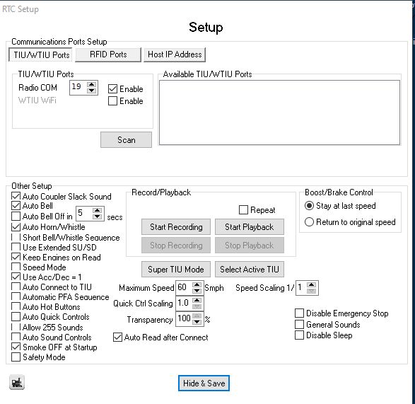 |
After
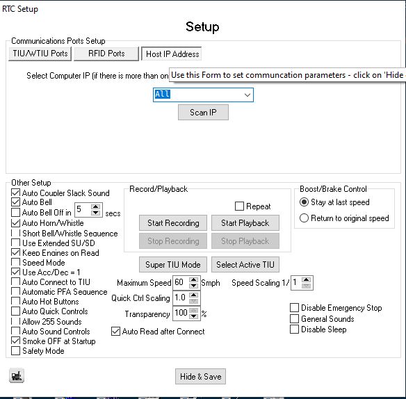
you start the program, press the [Setup │▼] button. You will
see this
window. To enable the RTC WiFi interface, click on the WTIU WiFi [X] Enable
check box. RTC will attempt to find all of the WTIU on your
network.
If it works, you will see all of the WTIU in the list box along with
their IP addresses and Ports.
If that doesn't happen, continue on, otherwise continue with Active TIU
selection in the next section. |
 |
If no WTIU appear, check that the smartphone app can
access the WTIU. If the app can access the WTIU, click on the Host IP Address tab. |
|
Click
on the downarrow "v" on the dropdown box. RTC will have already tried
to find the correct Host IP address. |
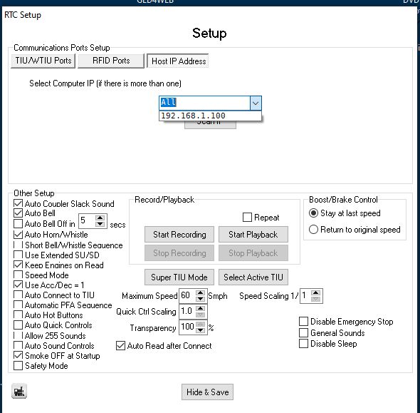 |
If
your computer
only has one Host IP address, RTC will select it automatically. If
there are several, choose the Host IP connected to the network that
your WTIU is on. If no Host IP addresses appear, presss the [Scan] button.
In this example, my computer is connected to one network. RTC will pick
that one automatically.
Once you select a Host IP address, RTC will remember your selection. |
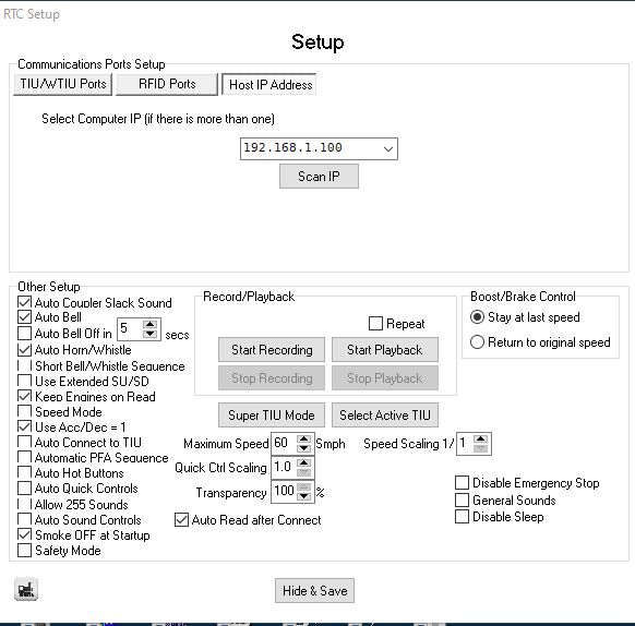 |
In
the dropdown, the correct Host IP address has been chosen. |
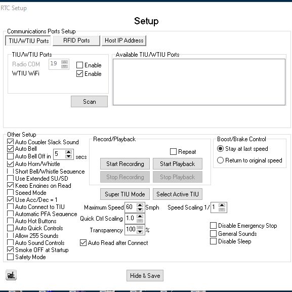 |
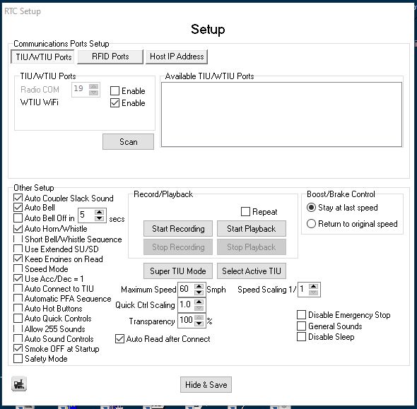
Then
click on the TIU/WTIU
Ports tab. Here we are going to pick the WTIU to
use.
First you need to enable the WTIU WiFi if it is not already enabled.
Check on the WTIU WiFi
[X]Enable checkbox.
If you don't see any WTIU listed, press the [Scan] button.
|
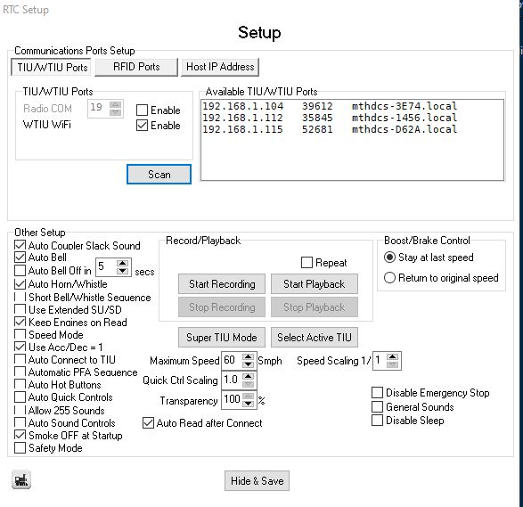 |
All
of the available WTIU will show up in the list box.
The WTIU identifies itself as "mthdcs-XXXX" where the "XXXX" is a four
digit hex number. The ".local" just indicates that it is my local WiFi
network.
If all of your WTIU don't appear, press the [Scan] button again.
(For you techy types, this is side effect of the mDNS
Ethernet protocol used to find the WTIU's. Even with the cell phone
App, all WTIU's may not be found without repeatedly scanning for them.)
You don't have to select anything here. In the next section, you will
set the active TIU.
When you are done, press [Hide
& Save].
|
The “Select Active TIU”
menu from the Setup window
For both
Radio COM mode and WTIU WiFi mode, you must
tell RTC which
TIU numbers are to be used. Press the [Setup │▼] button then press
the
[Select Active TIU]
button. Turn on the TIU numbers to be used by
RTC. At least one TIU must be selected.
You can
also access this menu from the dropdown arrow on the [Setup │▼] button.
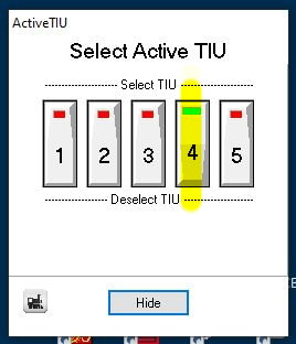 <--- Showing TIU 4
selected as the active TIU.
<--- Showing TIU 4
selected as the active TIU.
In WTIU
WiFi mode,
the program will display an error message if all of the selected TIU
are not found.
In Radio
COM mode,
this check is not done.
Starting RTC
Click on [Connect] and RTC will connect to your
WTIU. If
RTC can’t find all of the WTIU you have selected, press [Disconnect]
fix the problem and try again.
In WiFi mode, RTC will report an error if a
selected WTIU is not found when you press the [Connect] button.

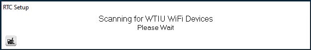
You need at least 1
WTIU but RTC can handle up to 5. You may see these messages as RTC
scans for WTIU and RFID train detectors:


Press the [Read │▼]
button. RTC will interrogate every WTIU in the “Active
TIU” list
and gather information about each engine found. These engines are
marked active. Engines that have been previously found but are now
missing, are marked inactive (option selected by “[x] Keep Engines
on Read”). An inactive engine is noted with an
italic font.
Here are some screen examples:
 |
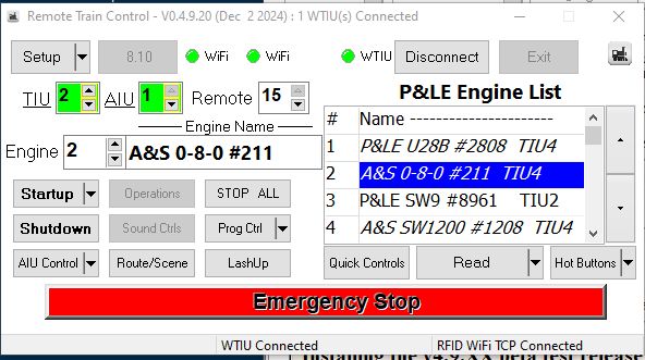
At the main RTC
window, you should see the red WiFi indicator and
the red WTIU indicator. This means you are not connected via WiFi yet.
The TIU spinner is not used at this point but you should select the
Active TIU you are using so you get the correct color indication.
Press the [Connect]
button. |
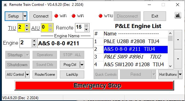
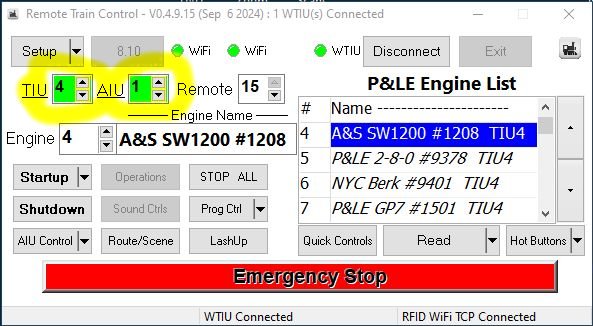
|
Now the WiFi and WTIU indicators both turn green
followed by the TIU and AIU spinners turning green. This indicates that
RTC is connected and ready to go.
Press the [Read │▼] button to fill the
Engine List with all of the engines on your layout, then select an
engine and press the [Startup]
button.
You can learn about the RTC program on this web page:
http://www.silogic.com/trains/RTC_Running.html
Videos to show you how to get started are here:
http://www.silogic.com/trains/RTC_Running.html#get
Download the program from here (but V5.0.0 may not be there yet). Email
me if you want to beta test it.
http://www.silogic.com/trains/RTC_Running.html#RTC_Download
|
What good is the TIU Spinner now that the [Read │▼]
button associates the engine with its TIU number automatically?
The TIU
Spinner is
the box under the [Setup │▼] button on the RTC
main window. You can set
a TIU number from 1 to 5.
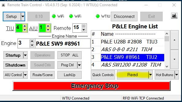
Since
each engine
has its TIU number assigned by the [Read │▼]
command, the value
in the TIU spinner is only used for a few operations.
1. If
the TIU number
in the Spinner corresponds to the TIU that you are connected to, the
spinner, along with the AIU spinner, will light up green.
TIU number 4 shows green
as it is the active TIU and is connected --->
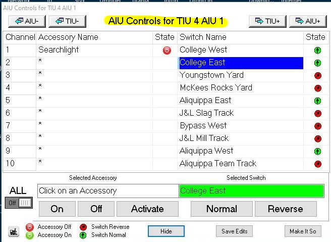
2. The
TIU spinner
(along with the AIU
spinner) is used when you open a AIU Control window. AIU window shown
below was opened by pressing the [AIU
Control │▼]
button on the main window above.
3. The
TIU spinner
is used by some of the debugging and testing commands when the main
RTC window is opened up in Debug mode.
Other Changes
Change #1 Handling of Engine Database
In the
older
versions, RTC could handle 100 engines for each TIU (for a total of
500 engines). The WTIU cannot do this – it handles a total of
97
engines for the entire layout. (Note that the number is 97, not 98,
99, or 100 due to the format of the layout interrogation command
–
which might be an error in the original TIU software.)
RTC
versions v1 to v4 had 5
“EngineDataX.ini” files – now there is
one “EngineData.ini”
file which holds the information for the 97 engines along with a new
piece of information, the TIU number they are associated with. Other
than
the addition of the TIU number, the format of this file is the same
as the older version.
With
these changes
the [Read │▼]
button on the main RTC windows becomes very important.
Now, every engine carries along the TIU number where the [Read │▼]
button last discovered it. This value defaults to zero so if you try
to control an engine before it is discovered, RTC will display an
error message. Since the TIU number
associated with an Engine is important, the TIU number is
displayed along with the
engine name in the Engine List and in the Popout Engine List. The TIU
number associated with the head engine of a lashup is displayed along
with the lashup name in the Lashup List and in the Popout Lashup List.
You should press the [Read │▼]
button each time that you startup RTC especially if you are using more
than one TIU. That is because of the possibility that an engine could
be on a track controlled by a different TIU than previously. The [Read │▼]
button is not so important after the first press if you are using only
one TIU.
Once connected, the TIU Spinner shows green and the
[Read │▼
] button can be
pushed.
When the read is complete, the engine list is filled with all found
engines on all active TIU.

The Lashup List will show the TIU associated with the head engine of
the lashup.
All engines in a lashup must be on the same TIU (unless running in
Super TIU mode).
Change
#2 All Engine Operation
When you
start All
Engine Operation, only active engines participate.
In WTIU
WiFi mode,
RTC effectively sets all TIU into Super TIU mode so all engines on
the layout will respond. In Radio COM mode, All Engine Operation
works with one TIU only as selected by the TIU Spinner.
Change
#3 AIU operation
On an
AIU window, if
you turn on the “ALL” switch and press an action
button, that
button will affect all Accessories or all
Switches on
all AIU on all TIU. This mimics
the operation of the
App.
The
older versions
of RTC would affect only the accessories and switches on the TIU
displayed. I previously changed it from that to affect only
accessories and switches on the one AIU displayed. With help from one
of the beta testers, I’ve changed RTC to function more like
the
App.
The
“ALL” switch
is reset to off after the action is complete to prevent double
action.
You can
use the
[Make It So]
button to set all accessories and all switches on this
AIU to the State shown on the grid.
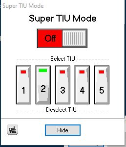
Change
#4 Super TIU Mode Menu
You can
now access
this menu from the dropdown arrow on the [Setup │▼]
button as well as the button on the Setup Window.
You must be connected to the WTIU's to change the settings on this
window.
Change #5 Watchdog Signal Support
What is the
Watchdog Signal?
MTH Engines can run in both conventional and command modes.
Conventional mode is like engines of the past. Using a transformer with
a big knob to control the speed. The engines can also run in command
mode where all control is from the TIU or WTIU.
Engines know which mode to enter because when the TIU or WTIU is
powered on, it sends a signal called a watchdog signal over the track.
When the engines see this signal, they enter command mode. If they
don't see that signal when they first receive power, they come up in
conventional mode.
This is fine when you power up your WTIUs along with your entire
layout. All of your engines will come up in comman mode. The problem
comes up when you have power going to sidings through a switch and you
have the switch off when you power on the WTIU. Then if you flip that
switch later to apply power to the siding, there is no watchdog signal
and the engines come up in conventional mode.
There are three
ways to generate a Watchdog signal:
I.
Generating a watchdog signal manually from the RTC menus using a
separate power switch for the siding
First, connect the power to a siding through a switch on your control
panel.
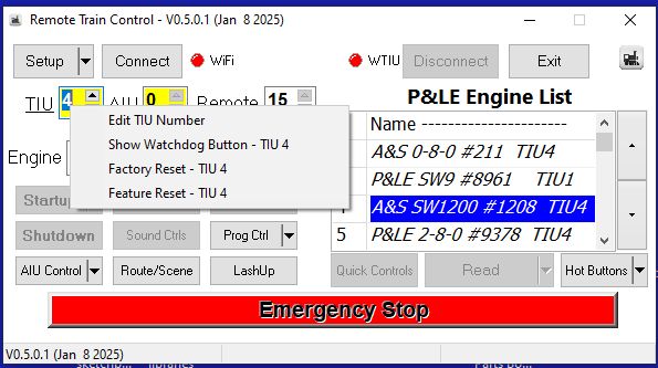
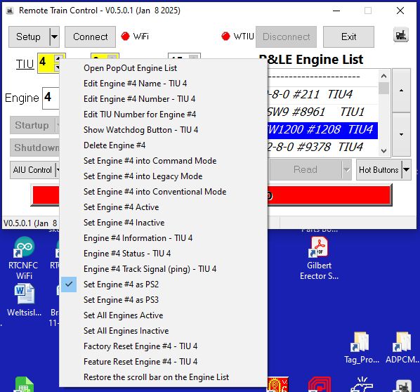
There is a new window called a Watchdog window. You can bring up this
menu two ways:
1. Right click on the TIU Spinner and
select "Show Watchdog Button" for the selected TIU.
2. Right click on an engine in the
Engine List and
select "Show Watchdog Button" for the TIU associated with the selected
engine.
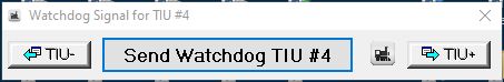
A new window, the "Watchdog Signal' window will display.
When you then click on the "Send Watchdog" button, several things will
happen in sequence:
1. The program will wait 3 seconds to
give you time to get your finger on the power switch for the siding.
2. The program will beep.
3. A soon as you hear the beep, flip the
power switch.
RTC will send a watchdog signal over the WTIU to let any newly powered
engines come up in command mode. The active and inactive engine counts
will be updated as returned by the Counts() function.
The watchdog button will only activate engines that have previously
been added to the Engine List by the [Read │▼] button.
II.
Generating a watchdog signal from AIU Controls window letting the RTC
program control power to the siding
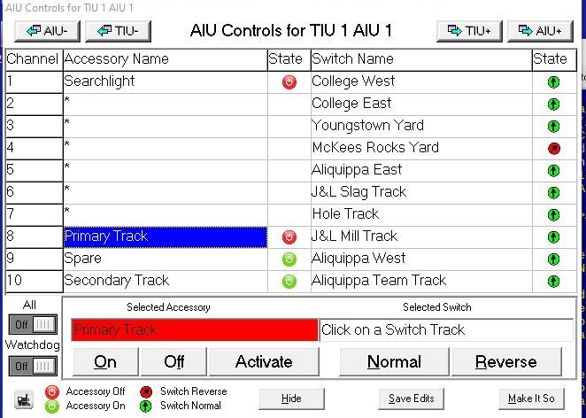
First, connect the power to a siding through an accessory channel on an
AIU.
On the AIU Controls window, name the channel that controls the siding:
Here, I've wired up TIU1 AIU1 Channel 8 to control the siding. Power is
off.
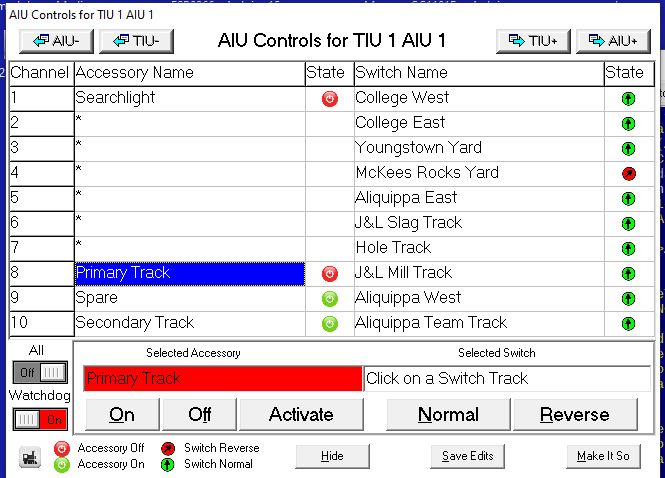
To generate an Watchdog signal, move the Watchdog toggle switch to the
"On" position. Then select channel 8 and press the "Selected Accessory"
[On] button. (Note that the watchdog is not generated and the toggle is
reset if you press the [Off] or [Activate] button.)
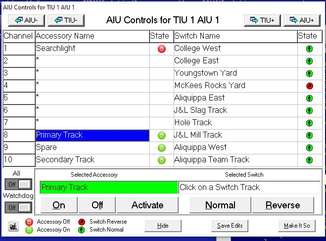
Channel 8 is activated and the siding receives power. Within 1 second
or so, the Watchdog signal is sent over the tracks. Your cursor will
spin for the short time that this taakes. Any newly powered up engines
sitting on the siding, see the Watchdog signal and power up in command
mode so they will sit quietly wating for a [Startup] command.
The "Watchdog" toggle switch automatically resets to "Off". If you
select other sidings, you must turn the "Watchdog" to the
"On"
position for each one.
III.
Generating a watchdog signal programmatically using the RTC Control
Language to control power to the siding
First, connect the power to a siding through an accessory channel on an
AIU.
Here is an example script, Watchdog.lua, that shows how to
generate a Watchdog signal:
|
Here is a listing
of the Watchdog.lua
script file
--[[
---------------------------------------------------------------------------
Remote Train Control Program for Windows

© Copyright 2025 by Mark DiVecchio

	This file is part of Remote Train Control.

	Remote Train Control is free software: you can redistribute it and/or modify
	it under the terms of the GNU General Public License as published by
	the Free Software Foundation, either version 3 of the License, or
	(at your option) any later version.

	Remote Train Control is distributed in the hope that it will be useful,
	but WITHOUT ANY WARRANTY; without even the implied warranty of
	MERCHANTABILITY or FITNESS FOR A PARTICULAR PURPOSE. See the
	GNU General Public License for more details.

	You should have received a copy of the GNU General Public License
	along with Remote Train Control. If not, see <http://www.gnu.org/licenses/>.

 Home Page : http://www.silogic.com/trains/RTC_Running.html
---------------------------------------------------------------------------]]
-- Semicolons are not required in Lua code
title = "Watchdog"
require([[defines]]);
require([[functions]]);

--[[
When using this module, all variables (including functions!) must be declared through
a regular assignment (even assigning nil will do) in a strict scope before being used
anywhere or assigned to inside a nested scope.
https://github.com/lua-stdlib/strict
]]
local _ENV = require 'std.strict' (_G) -- strict.lua will detect undeclared global variables
local _;

local MyEngineNo, MyTIUNo;
title = "Watchdog Test"
local iChan, iAIU;
iChan = 8;
iAIU = 1;
--
-- Note that there is no loop() function in this sketch
-- All actions are initiated by the buttons
--
--[[---------------------------------------------------------------------------------------]]
function setup(Engine, TIU)
	MyEngineNo = Engine;
	MyTIUNo = TIU;
	--
	print(string.format("setup(): Debug level %d", Debug()));

	print("setup : TIU " .. MyTIUNo .. " Engine " .. MyEngineNo .. " Debug " .. Debug());
	assert((MyTIUNo >= 1 and MyTIUNo <= 5),"TIU Number out of range");
	print("setup : AIU " .. iAIU .. " Channel " .. iChan);

	return true; -- false=setup failed, true=setup succeeded
	end

--[[---------------------------------------------------------------------------------------]]
function cleanup()
	-- this function is called once when the user presses the [STOP] button or the Stop() function is called
	print("cleanup : TIU " .. MyTIUNo .. " Engine " .. MyEngineNo .. " Debug " .. Debug());
	local iResult = OffButton();
	return iResult; -- false=cleanup failed, true=cleanup succeeded
	end
--[[---------------------------------------------------------------------------------------]]
function OnButton()
	print("Track Power On : " .. GetAccName(iChan, iAIU, MyTIUNo));
	-- energize track
	if (Siding(ON, iChan, iAIU, MyTIUNo) == nil) then
	print("Siding Power On failed");
	return false;
	end;
	return true;
end
Function01Name, Function01Label = OnButton, "Track Power On";
--[[---------------------------------------------------------------------------------------]]

function OffButton()
	print("Track Power Off : " .. GetAccName(iChan, iAIU, MyTIUNo));
	-- deenergize track
	if (Siding(OFF, iChan, iAIU, MyTIUNo) == nil) then
	print ("Siding Power Off failed");
	return false;
	end;
	return true;
end
Function02Name, Function02Label = OffButton, "Track Power Off";
--[[---------------------------------------------------------------------------------------]]
function WatchdogButton()
	print("Watchdog : TIU #" .. MyTIUNo);
	-- Send Watchdog signal
	if (Watchdog(MyTIUNo) == nil) then
	print("Watchdog failed");
	return false;
	end;
	return true;
end
Function03Name, Function03Label = WatchdogButton, "Watchdog";
--[[---------------------------------------------------------------------------------------]]
|
Look at the function "OnButton()".
This function is the brains of the script. It calls the new "Siding()" function.
This function does several things:
1. The acccessory channel given by the
parameters
iChan, iAIU and MyTIUNo, is turned "ON". This applies power to the
siding.
2. The engines power on.
3. RTC then sends a watchdog signal over
the TIU
4. The engines come up in command mode
and can be used by RTC just as any other engine.
5. The active and inactive engine counts
will be updated as returned by the Counts()
function.
Look at the secondary function "WatchdogButton(). It calles the new
"Watchdog()" function. It does one thing:
1. Causes RTC to send a watchdog signal
over the TIU.
The watchdog button will only activate engines that have previously
been added to the Engine List by the [Read │▼]
button.
WIU/WTIU Packet
Here is a utility program that might help you confirm
that your
WIU or WTIU setup is correct. You can download this program from this
DropBox link:
https://www.dropbox.com/scl/fi/nraldxoitwxi4hkyn584g/WIU2.zip?rlkey=ylx6ex4lyhowbyb3ztpwnm5m6&st=yscmwkgg&dl=0
Just start it
and you should see a list of the found WIU/WTIU in the upper right list
box.
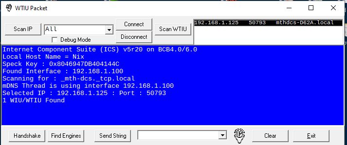
If you
want to rescan your network again, press the [Scan WIU] button.
Press the [Connect]
button to create a WiFi connection the WIU that you select from the
list.
Press [Handshake]
and this program will show you the TIU number and
number of AIU connected to this WIU/WTIU. You might see something like
this:
WIU/WTIU TCP Sending Local
Port = 64629
Session Connected
H5 Response : H5
70973C94 okay
->
H6 Response :
H66499F4B2 okay
->
x Response : x33
-> TIU/WTIU
#4 with 3 AIU(s)
The [Find Engines]
button will ask the TIU about the engines connected to
it. Along with some technical information, you will see all of
the engines
that are associated with that TIU.
P&LE U28B #2808
: Reading Engines - TIU #4 :
Engine # 1 of 18 Engine(s) Total
A&S 0-8-0
#211 : Reading Engines - TIU #4
: Engine # 2 of 18 Engine(s) Total
The [Send String]
button will send whatever string you type in the box to the TIU.
Checking the "Debug Mode" checkbox will display a lot of technical
information that may not be useful.
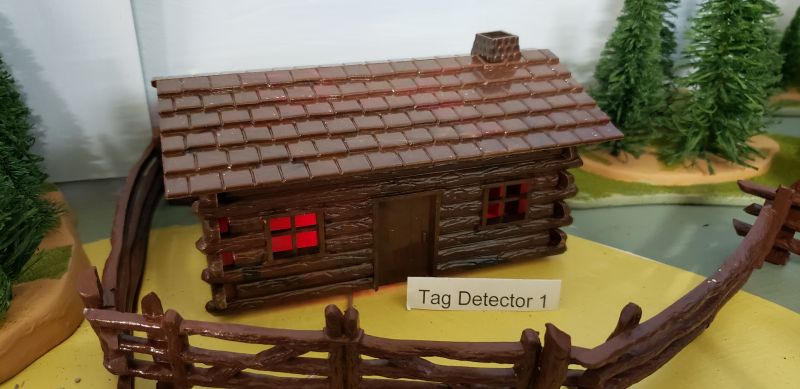
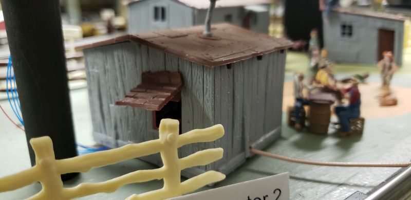
WiFi based RFID
Detectors (You
can skip the rest of this page if you don't use the RFID Detectors)
The other major WiFi change was moving my RFID detectors from RS-232
based wired connections to WiFi based connections.
These detectors functionally operate the same as the wired version. You
can look at this page for operational details. http://www.silogic.com/trains/RFID.html
The
ESP8266
Mike Hewett always seems to be acknowledged on my web pages and he
deserves
it. Mike learned about the ESP8266 based NodeMCU board and started to
use it in his projects. After I saw his success and how easy it was to
use, I started to rewrite my RTCNFCIRQ program to use that
device.
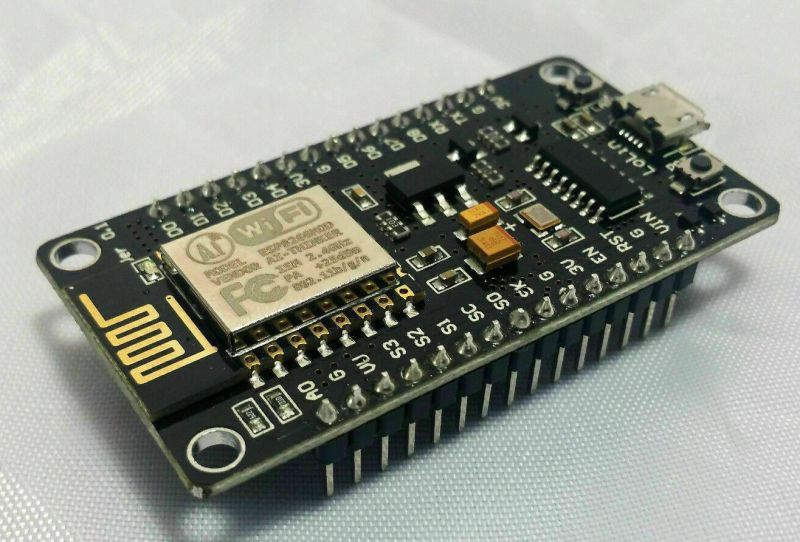
The ESP8266 is a small powerful computer connected to a WiFi Radio.
They are available from many sources on the Internet. Watch out for
knock-offs.
My Ideas
I figured that could replace the wired serial connections for my RFID
tag detectors (which send tag information to the RTC program). Read
about the current wired solution here: http://www.silogic.com/trains/RFID.html
Here is a photo of an ESP8266. I've been using the version with the
CH340 USB chip. These are around $5 each as of Feb of
2024.
Ported the
RTCNFCIRQ sketch to the ESP8266 - RTCNFCWiFi
The current version of the RTCNFCIRQ sketch runs on a
Seeeduino/Infiduino. This porting effort moved the sketch to run on an
ESP8266 and the sketch is now called RTCNFCWiFi.
These detectors functionally operate the same as the wired version. You
can look at this page for operational details. http://www.silogic.com/trains/RFID.html
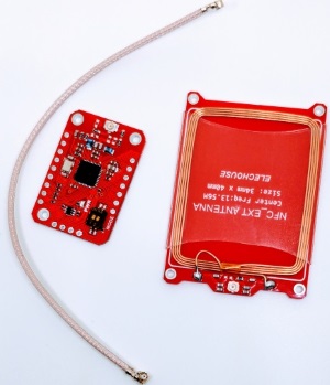
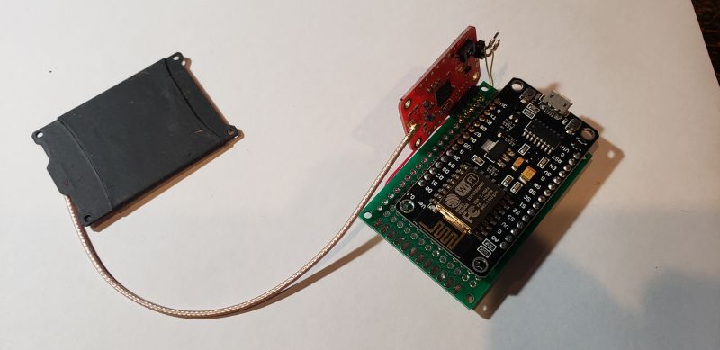
Here are a few photos of an ESP8266 wired to a PN532 RFID detector. The
black antenna is placed under the track (it was originally red but I
painted it black, like the Rolling Stones). This only requires
connection
to power. The assembly here is not critical. I've used up to 12 inches
of wire between the ESP8266 and PN532. The 6 inch coax cable between
the PN532 and the antenna should not be extended. I tried longer cables
but the performance suffered greatly.
 |

Again I have to thank Mike Hewett for reminding me of wirewrap.
My original test bed connections were done with what is call "Dupont"
wires. These are nothing more than wires with push on connectors on
each end. Nice and easy to use but prone to coming loose. Good for
prototyping. Mike showed me some of his work using wirewrap.
When
I started in the computer design business in 1970, wirewrap was still
common and acceptable even for production work.
Look here : National
Advanced Systems.
Mike used a hand wirewrap tool but I had a couple of very old
Gardner-Denver wirewrap guns. I dug them out and replaced the long dead
rechargable battery with 2 D cells and I was off. I used the small green
proto board from MPJA.com as a base. |
Sadly, these PN532 RFID detectors have doubled in price since pre-COVID
times. After having
tested many different detectors these are still the best functioning
detectors when placed under 3-rail track.
Cost:
ESP8266
$5.00
Tag Reader from Elechouse
$34.50
(as of Feb 2024) If you buy 10, they are $29.00 each.
https://www.elechouse.com/product/pn532-nfc-rfid-module-w-external-antenna-updated-version/
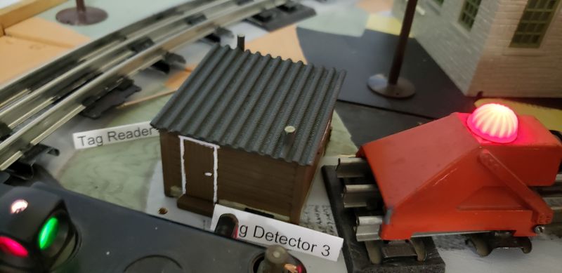
The ESP8266 has enough pins to control two tag readers. I have 13 tag
readers on my layout controled by 8 ESP8266.
| Signal
Name |
ESP8266
Pin |
Elechouse PN532 RFID Module #0
Pin |
Elechouse
PN532 RFID Module #1
Pin |
| VDD/VCC |
3V |
VDD/VCC |
VDD/VCC |
| GND |
G |
GND |
GND |
| MOSI |
D7 |
MOSI |
MOSI |
| MISO |
D6 |
MISO |
MISO |
| S
Clock |
D5 |
SCL |
SCL |
| IRQ
#0 |
D2 |
IRQ |
-- |
| SS #0 |
D0 |
SS |
-- |
| IRQ
#1 |
D3 |
-- |
IRQ |
| SS #1 |
D1 |
-- |
SS |
Powering the Tag
Detectors
The ESP8266 can be powered by 4.5 - 20 VDC applied between the VIN pin
and ground. The ESP8266 will regulate that down to 3.3 VDC for itself
and
for the PN532. You can use any method you want to get the voltage to
the VIN pin. I used an AC to DC converter getting power from the
closest 3-rail track. I have also used a dedicated power supply.
RTCNFCWiFi
source code and pre-compiled binary
I'll
try to keep this zip file up to date but if you are going to
seriously work with it, email me to be sure you have the latest
version.
RTCNFCWiFi
V4.5 - This
is an ESP8266 NodeMCU based sketch using WiFi to connect RFID tag
detectors to the RTC program.
Right now, this sketch is one ZIP file. You can
download it here.
The ZIP file has a precompiled *.bin file
which can be downloaded into the ESP8266.You must use a USB connection
to load this sketch into the
ESP8266 the first time, after that, you can use the Over The Air (OTA)
connection - note that you don't have to use the OTA connection, you
can use the USB connection all the time.
Getting it into the ESP8266 is fairly easy- here is how to do the first
time which requires a USB connection:
1. Connect the ESP8266 to your PC using
a USB cable.
2. Drivers for the ESP8266 should
automatically load
3. Note the COMx port that the ESP8266
connects as or use Device Manager to locate the port number..
4. Extract the above ZIP file into
a folder (just create a new folder somewhere).
5. Open a command window at the folder
where you put the files
6. Using notepad, edit the file
USB.bat. Change the
serial port number (from "COM3") to the serial port number where
the ESP8266 connected.
7. Run the
USB.bat file or
manually type in the following command after changing the serial port
number:
.\esptool.exe --baud 115200 --port COM3 write_flash --flash_mode qio 0x00000 RTCNFCWiFi.ino.nodemcu.bin
To use the OTA method (after the first time using USB)
1. Extract the above ZIP file into
a folder (you can use the same one you created above)..
2. Open a command window at the folder
where you put the files
3. Using notepad, edit the file
OTA8.bat.
Change the IP address to the IP address of your ESP8266. You can get
the IP address from RTC after you use the device for the first time
(Look in the Setup window..
4. Run the
OTA8.bat file or
manually type in the following command after changing the IP address:
.\python3\3.7.2-post1\python3 -I .\espota.py -i 192.168.1.114 --auth=esp8266 -f .\RTCNFCWiFi.ino.nodemcu.bin
If you try to compile this yourself, I used the Arduino IDE
portable version 1.8.16. You will have to download that version of the
IDE, install it and then
install the ESP8266 library. After that, download and
manually install the following additional
libraries:
Needed for all sketches (From the
Arduino IDE, use
the Sketch->Include Library->Manage Libraries, find the
library
and hit [Install]):
ESP_DoubleReset_Detector v1.3.2 by Khoi Hoang
ESP8266TimerInterrupt v1.6.0 by Khoi Hoang
After that, download and manually install
the following additional
libraries into the IDE portable library folder (on my computer :
C:\arduino-1.8.16\portable\sketchbook\libraries):
Needed for all sketches:
RTC_NFC by Mark
DiVecchio. Download
library
from here.
Needed for RTCNFCWiFi
PN532_SPI by
Adafruit Industries and Seeed Studio, modified by Mark DiVecchio
PN532_modified by Adafruit Industries and Seeed Studio,
modified by Mark DiVecchio
NDEF by Adafruit Industries and Seeed Studio
Original at
https://github.com/elechouse/PN532
Download modified
library
from here.
RTC RFID Tag
Detection Configuration
When you first load the ESP8266 with the program, it must connect up to
the WiFi router (so we need the SSID of the router and the password)
and you must tell it what detector number it is and how many
tag readers are connect to it.
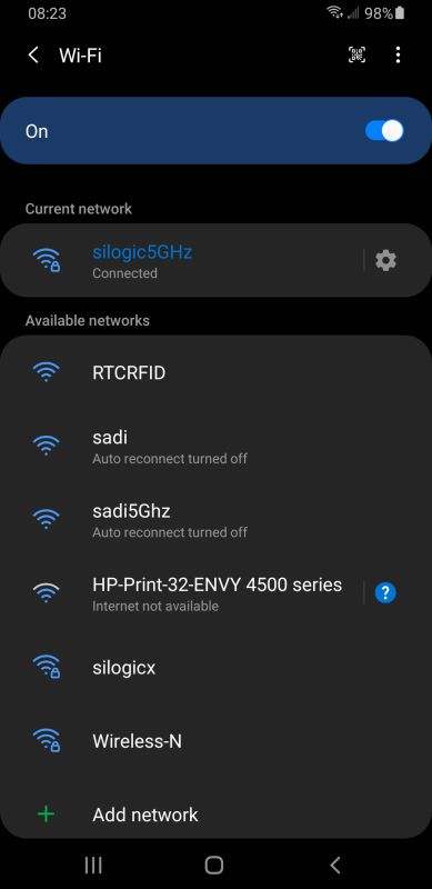
This is done by connecting to the ESP8266 from your phone. Tap on your
WiFi icon and follow along:
|
After you download
the RTCNFCWiFi program into the ESP8266, it will
start an Access Point. If you look on your phone, you will see the new
WiFi
AP listed as RTCRFID. Tounch on that AP to connect to it.
|
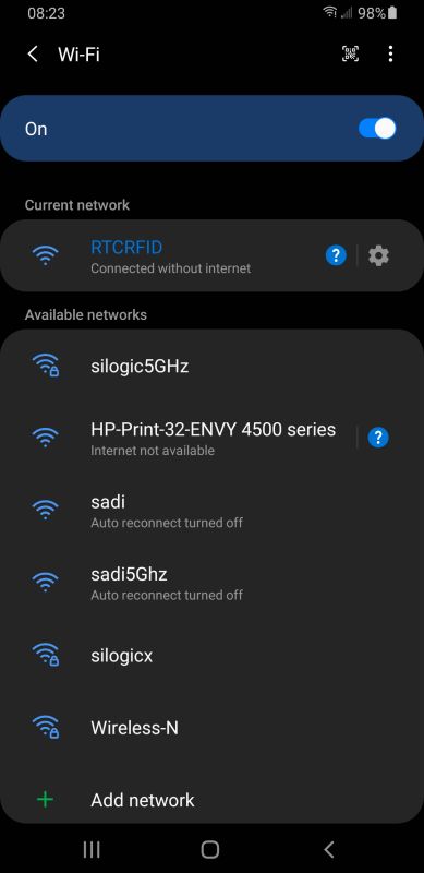
|
The
phone should connect up and you should see the RTCRFID AP "connected
without internet".
|
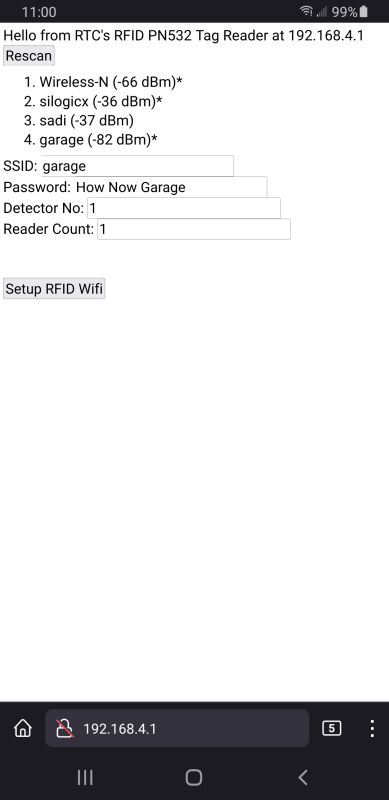 |
Then
startup a web browser such as Firefox or Chrome. Enter this IP
address into the Address Bar: 192.168.4.1 . Press
GO. You should
see this screen which lists all of the accessible routers in the area.
Here is were we enter the information that the
RTCNFCWiFi program needs to communicate with your computer via the WiFi
Router.
Enter:
The SSID of your router
The WiFi password of your router
The detector number of this device
The number of tag readers connected to this device.
Then click on [Setup RFID WiFi]. |
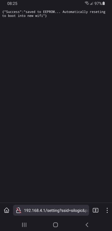 |
You
should see this screen indicating that the device is rebooting and will
connect up the WiFi Router. |
You have to do this with all of the RFID tag detectors on your layout.
Be sure that the detector numbers are unique. Then the detectors are
ready for use by RTC.
This site prepared and maintained by Mark
DiVecchio
email : markd@silogic.com
SD&A
HOME
Mark's Home Page
The DiVecchio
genealogy home page
The Frazzini
genealogy home page
This site will be under construction for a while.