Mark DiVecchio's O-Gauge Train Layouts
Train Detection
using PN532 RFID Modules
This Page last updated on
.
On this page, I describe the work that I've been doing to implement a
method
of train detection on my layout. My layout uses 3-rail tubular track so
all of the work that I've done is with that kind of track. I expected
to
see (and I did) that the metal track would affect the operation of the
tag reader.
This is based on the work that I did for the Remote
Train Control (RTC) program and OOK Radio Support.
For help and other ideas, join the RFID For
Model Railroading Yahoo! group.
 The
method described on this web page uses wired RS232 signalling to
connect all of the tag detectors to the RTC program running on the PC.
Once you understand how this works, you can look at http://www.silogic.com/trains/WiFi.html
where I now use WiFi signalling to connect the detectors to the RTC
program.
The
method described on this web page uses wired RS232 signalling to
connect all of the tag detectors to the RTC program running on the PC.
Once you understand how this works, you can look at http://www.silogic.com/trains/WiFi.html
where I now use WiFi signalling to connect the detectors to the RTC
program.
Prior Art
Two people that I've been working with have implemented schemes to do
train detection.
Mike Hewett
Mike has implemented a scheme where the tag reader is inside of a car.
The tags are mounted below the track. The tag reader detects a tag and
sends a response via a Zigbee
radio to the control computer.
Ray Leiter
Ray's implementation uses a tag reader under the track (he uses
FastTrack) with tags mounted under the engine.
Here is a video (#1) that Ray did showing his work:
Image loading....
Video #1 - Ray's
Implementation
Ray has an RFID tag reader under the track. It connects to an Arduino
and an Elechouse CC1101 radio. He has the Arduino programmed to send
out an SXS command each time a train is detected. He uses the UID on
the tag to know which engine was detected so that SXS command addresses
the right engine.
Seth Neumann and Chris Drome
This document
describes an RFID implementation in HO. Doing it in HO gauge is much,
much harder.
My Ideas
I'm looking at an implementation similar to Ray's. I envision a scheme
where there are RFID tag readers at strategic places around the layout.
RFID
tags
are attached underneath every engine and car on the layout. Tags are
loaded with information about the engine/car to which they are
attached. A control computer could then use that tag information to
control the engines.
I would use the radio and commands that I developed for the RTC program
using OOK transmission codes.
Needs to be cheap. I chose the 13.56 MHz tags that support
the ISO14443 standard commonly called MIFARE Classic.
I plan to put two tags on each engine, one on the front truck and one
on the rear truck. Cabooses will have one tag on the rear truck. All
other cars will have a tag on one of the trucks. I plan on each
tag having information about its distance from the end of the car. I
hope to be able to couple/uncouple, pickup
and drop off cars
automatically via the control computer.
So what can we do with this. I envision a "smart" Master Control
program which
gets the tag information and controls the trains. Say, for example, you
are running one freight train, doing switching to drop off and pick up
cars. Let a computer run another freight train in the other direction.
The computer would know where your train is and control the other train
to take sidings to keep out of your way.
Or maybe, the computer controls a 1st class
train over the layout
while you, controlling a peddler freight, have to figure out how to
keep out of the way of the 1st class train while
still doing your work.
Here
is link to a paper that describes basics of the use of these
readers.
Hardware
Here is the hardware that I looked at and the hardware that I finally
selected.
RFID Tag readers
I looked at three different types of RFID tag reader boards. They all
operate at
5v although they might operate well enough at 3.3v.
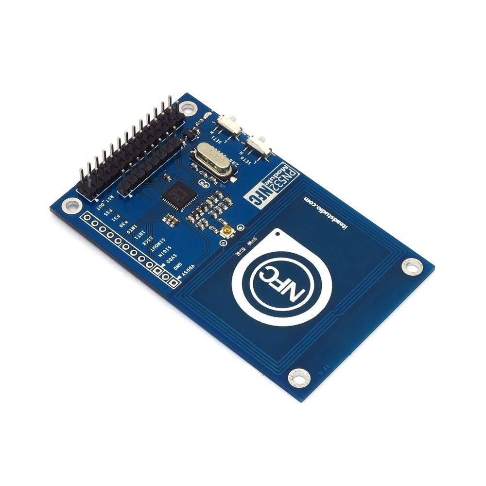
Blue PN532 NFC
Board
I bought this board on eBay
(search
for PN532). It has the antenna
adjacent to the circuitry. I attached it beneath the track with the
"NFC" logo under the tracks, facing up. This is a 3.3v board. It has a
5v to 3.3v voltage regulator on it. SPI inputs must be 3.3v levels.
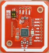
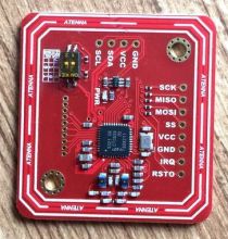
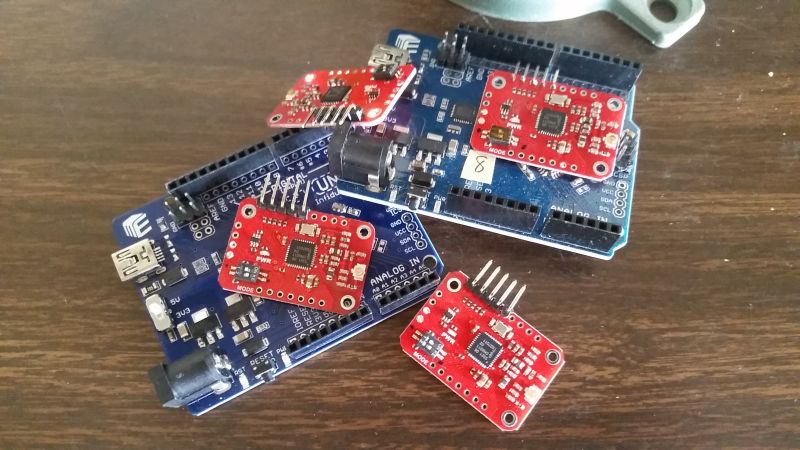
Red PN532 NFC single board implementation by Elechouse
These boards are from Elechouse.
The antenna surrounds the circuitry. I attached it beneath
the
track with components facing downward. Be warned that there are many
knockoffs of this board on eBay. I tested both the genuine board from
Elechouse and a
knockoff board from China. Be very careful not to short
the printed circuit board etches to the track. I did and burned out the
NFC board and the attached Arduino. According to their web page :
"On-board level
shifter, Standard 5V TTL for I2C and UART, 3.3V TTL
SPI" and "SPI:
3.3V TTL with 100 ohm resistors in series. It could be
connected directly to 5V interface of microcontroller such as Arduino."
(Mark's note: 100 ohm resistors AKA the poor man's level converters.)
In Mar
2020, I tested the V4 reader and the results are below.
PN532
NFC RFID module V3:
PN532
NFC RFID module V4:
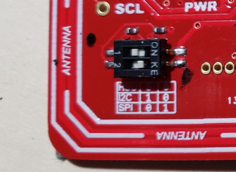
The mode switches must be set correctly for SPI mode to work with my
software. Maybe hard to see in the photo : switch 2 must be toggled to
the right. Remove the thin plasitic cover to do this. I put little
black ink dots on the board to remind me of the switch positions.
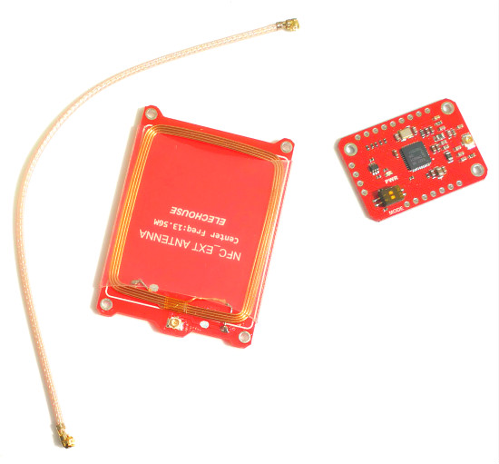
Red PN532 NFC board with External Antenna by Elechouse
This board is from Elechouse.
I attached the antenna under the track with antenna side
facing downward. According to the web page : "On-board level shifter,
Standard 5V TTL for I2C and UART, 3.3V TTL SPI" and "SPI: 3.3V TTL
with 100 ohm resistors in series. It could be connected directly to 5V
interface of microcontroller such as Arduino." As
of Sep of 2021 they are $21.50 or 10 for $18.50 each. Definitely a
post-pandemic price.  Well I thought that the 2021 price was high ----- in August of 2022,
the price is $34.50 or 10 for $29.90 each. Supposedly because NXP is no
longer making the PN532 chips.
Well I thought that the 2021 price was high ----- in August of 2022,
the price is $34.50 or 10 for $29.90 each. Supposedly because NXP is no
longer making the PN532 chips.
Elechouse
sells longer coax cables for these readers. This would let you put the
reader near the Arduino under the layout and just run the coax up
through the train board. The reader comes with a 15cm (about 6") coax.
For a few dollars, you can get 30cm (12"), 50cm (20") and 100cm (40")
coax. As of March 2020, I report
on their performance below.
The two PN532 board types (single board and external antenna)
from
Elechouse are electrically identical except for the location of the
antenna. The same
Arduino software will control either version.
The small mode switches must be set correctly on the reader to work
with my software. Look at the photos in the single board section.
Black RC522 Board by Maker-Hawk
This board is really cheap from China. The one I bought works but it
reports back as a "counterfeit" RC522 chip.
Below I discuss the detection range that I got with this device and why
I didn't use it.
Tags
I selected several different ISO14443 tags to test. All of these tags
could be
programmed with up to 768 bytes of information. They all operate at
13.56 MHz.
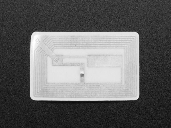
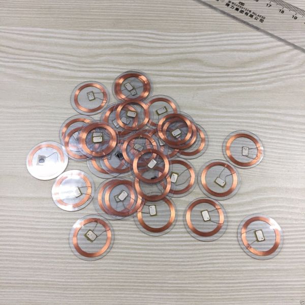
Found on eBay,
these transparent NFC tags were mounted on a 25 mm PVC disk. Others I
found were on an opaque white disk ($0.28 each minimum 100 pieces) I
also found a very similar tag from alibaba.com
("Mini Coin Tag/Token Tag Dia 25mm 13.56MHZ transparent Plastic NFC
coin tag") for $0.18 each minimum 100 pieces. These tags worked about
the same during my tests. I liked the transparent tags because they are
less visible when mounted under a consist. There are also some 18mm
diameter tags but I did not test those.
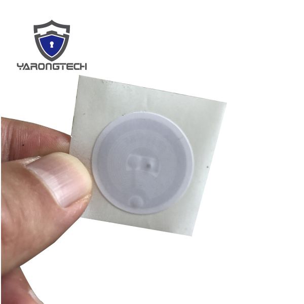
Found on
eBay, these white
sticker style tags with adhesive. 25mm(diameter)
This tag, from
Adafruit
was really small and would be especially easy to mount underneath
engines and cars. Size: 15.6mm x 6mm
Also from
Adafruit,
this sticker style tag. Size: 41mm x 24mm x 0.2mm / 1.6" x 1" x 0.008.
Per the Adafruit web page : "
Works
about 2.5" away from reader". Wow - that would be great,
but these tags were pretty large.
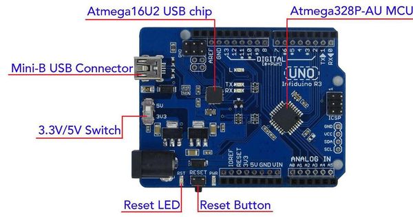
Arduino Uno with one Tag Reader Attached
I used a version of the Arduino called the Infiduino. It can
run
at both 5v and 3.3v so I could test the RFID tag reader
boards at both voltages.
Connection to the Arduino
All of the RFID tag readers that I tested can connect to the Arduino
three different ways. I used the SPI (Serial
Peripheral Interface) method. SPI uses a simple
synchronous serial communications with a separate select line. The
other connection methods HSU (High Speed UART) & I2C (Inter-Integrated Circuit) only allow
one tag reader per
Arduino.
Using the SPI required small switches on the tag reader board to be
changed (the boards default to RS232 style HSU serial connection).
SPI uses four signal lines plus 5v power and ground. Three common
control lines connect to all SPI devices attached to the Arduino. They
are
SCK, MISO and MOSI. The fourth signal line, SSn/CSn (also called
SCL), is a chip
select line
which is unique to each SPI device. I used the ICSP header for the
three common control lines :
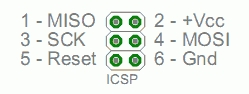
I connected the SSn/CSn pin of the tag reader to pin 10 on the Arduino.
I
conected the other three SPI pins to the ICSP header on the Arduino.
Look at the drawing above for MISO (pin 1), SCK (pin 3) and MOSI (pin
4). I then used +VCC (pin 2) and ground (pin 6) on the ICSP header.
First Tests
Download and install the latest Arduino IDE.
The Arduino required libraries to interface with the RFID tag reader
boards. There are several libraries floating around. The one I used can
be downloaded
from here. The downloaded file should be named
PN532-PN532_HSU.zip.
Once you unzip the file, you should have five folders inside of a top
level folder. Move these five folders into your Arduino Libraries
folder (usually at :
C:\Users\<username>\Documents\Arduino\libraries).
The five folders are:
NDEF
PN532
PN532_SPI
PN532_HSU (not used but gets loaded with
the whole library)
PN532_I2C (not used but gets loaded with
the whole library)
I wrote a simple test program based on the examples in the Arduino
PN532
library. Using the Arduino IDE, I displayed each tag as it was
detected. I mounted each tag reader underneath the track. I mounted the
tag at the lowest spot on the engine that I used. Knowing that the
metal of the engine would affect the operation, I mounted the tag with
double sided foam tape so that as much of the tag as possible was in
"free air" and not near metal.
PN532 vs RC522 Boards
The major selection point, which came to the front as I developed the
software described below was that the PN532 could be programmed to sit
and wait for a tag to come into range at which time it would interrupt
the Arduino. The Arduino could be off doing other things most of the
time. The RC522 board required that the Arduino continuously poll it,
asking
if a tag came in range. It is important that the Arduino have time to
do other tasks as you will see when you look at the communications
scheme I developed.
Test Results
There were clear winners. First the really large tag worked the best -
it was detected at ALMOST 2 INCHES!
But it was too hard to mount inconspicuously under the engine or car.
The smallest tag did not detect at all. The tag in the transparent PVC
mounting was the best for its size. It was solid enough to be able to
extend
into
"free air" without distorting and it detected at about 1 inch. The
round white tags were too floppy and
tended to get "picked" by the switch tracks on my layout.
Update: Elechouse
came out with a V4
of their PN532 single board reader
which I receieved in March of 2020. I tested this board and I am
really impressed. Detection range was 1.5 inches with the transparent
PVC tags.
I found an unusual mode of operation though. As the tag
passed over the reader, it was detected correctly but as it exited the
reader's RF field, it would be redetected. This is not good.
That made
this board unusable
on my layout.
|
The knockoff Chinese PN532 board had a detection range
of about 0.5 inches. A VERY noticeable reduction. Stay away from the
red knockoff PN532 readers.
The blue PN532 reader had a detection range of about 0.5 inches. Not
good enough to read through tubular track.
I tried the tag reader boards with the Arduino running at both 5V and
3.3v. There was no
detectable operational difference between the voltages.
The RC522 board from Maker-Hawk had a detection range of about 0.5
inches. Not good enough to read through tubular track and is not
software
compatible with my scheme.
Update:
The Elechouse reader with the external antenna comes with a 15 cm coax
connecting cable. As I report above, I saw a detection range of about 1
inch. I got some longer cables to check the performance. Longer cables
would
be nice to reach into more difficult areas of the layout. The results
were disappointing and probably means I can't use longer cables.
| Cable Length to external antenna |
Detection Range |
| 15 cm |
1.00 inches |
| 30 cm |
0.75 inches |
| 50 cm |
0.50 inches |
| 100 cm |
not tested |
Elechouse single board reader V4 (0 cm cable length)
but unuseable, see note above |
1.50 inches |
Final Decision on the Hardware for the Detectors
For the hardware, it was clear that the Elechouse PN532 version with
the
external antenna and shortest cable was the best at detecting tags
through the metal
3-rail tubular track. It had a detection range of about 1 inch with the
transparent PVC tags.
Tag Reader Mounting
I found that the metal ties affected the
sensitiviy of the tag readers. The metal rails did not affect it that I
could detect. When I mounted the tag reader under a piece of O
straight track, I could mount it far enough away from the ties so that
the detection worked well. When I tried 0-72 curved track, the reader
barely fit between the ties and the ties reduced the sensitivity a lot.
So for track sections that did not have about 1 inch clearance for the
reader, I had to remove a tie or at least, move it over to give
adequate clearance to the tag reader.
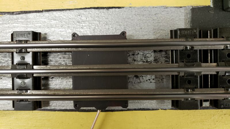
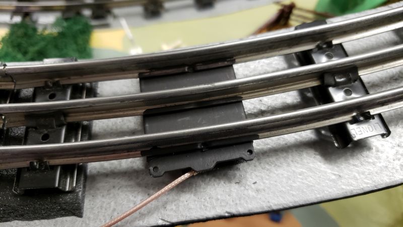
Here is a good mounting under a piece of O straight track.
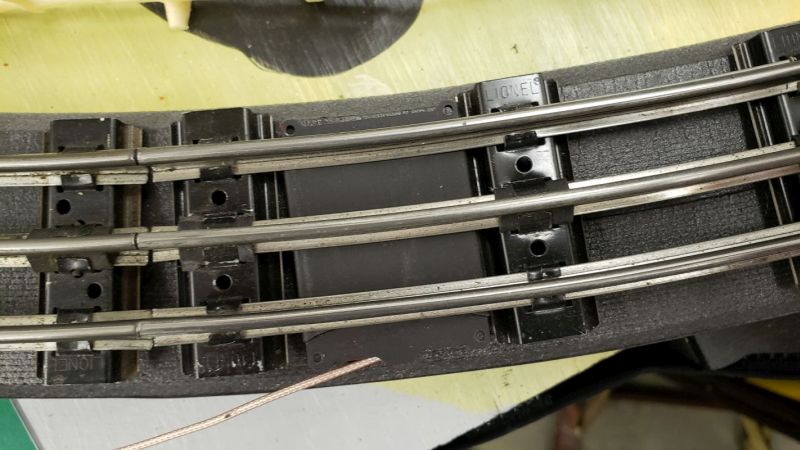
Here is a mounting on a piece of O-72 curve track. The reader did not
work well here.
Here I've removed a tie and centered the reader between the remaining
ties
clearing them by about an inch or so. This arrangement worked well. I
painted the bottom lip of the track black. I might put some kind of
fake tie in place and when I ballast the track, this will look great.
Tag Programming
Once you pick a tag, it has to be programmed.
In each tag, I store 16 bytes of data about the Engine/Car and 16
characters of the name of the Engine/Car.
Look on this webpage
where I describe my programmer.
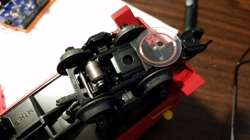
Tag Mounting
Here are some photos of tags mounted under engines and cars (using
black foam double sided tape):
Front Truck of an
Engine
|
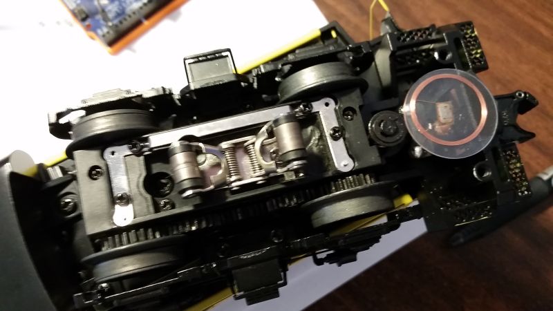
Rear Truck of an
Engine
|
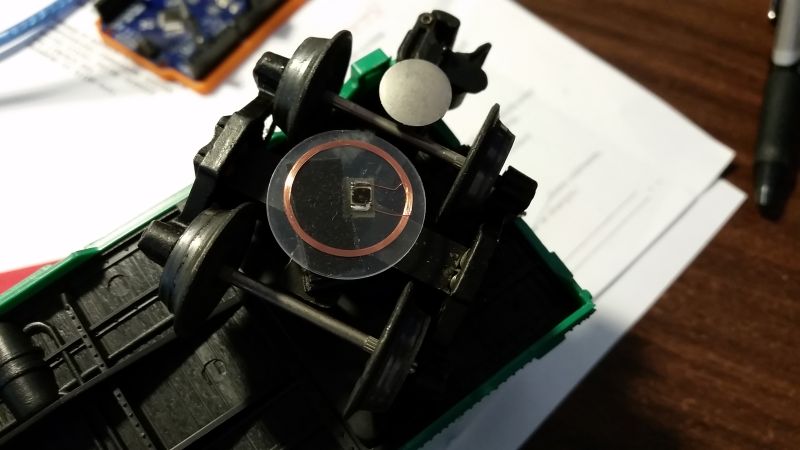
Boxcar
|
Rear Truck of a
Caboose (I want a tag at the very end of each train)
|
Arduino Uno with Multiple Tag Readers attached
One of my goals was to have multiple RFID tag readers attached to each
Arduino. The three common control lines (SCK, MISO, and MOSI) are
connected
between the Arduino and all the tag readers. The fourth control line
(SSn/CSn/SCL) is unique to each tag reader. SSn can be connected to
digital pins
2-10 and analog pins 0-5 for a total of 15 tag readers attached to each
Arduino.
The most I have tested is 4 tag readers. I'm thinking that one Arduino
would handle train detection for a passing siding. That would be 6 tag
readers, 3 each surrounding each of the two switches that make up the
passing siding. That way you can detect trains entering the leaving the
siding on all tracks.
Mark's note: later testing (which required modifications to the code)
caused me to limit each Arduino to 6
readers, see below.
Elechouse PN532 & NDEF Libraries
I had to edit two files in the PN532 library.
1. The library allocates a 255 byte
buffer for each tag reader. An Arduino with 15 readers would then
require
3825 bytes of RAM. Each Arduino Uno only has 2,048 bytes of
RAM so we
would have a problem.
Since each tag reader (in my code) is read sequentially, only one 255
byte buffer is actually needed. I made this change to the code:
From the PN532.h in the PN532 folder,
remove the declaration of
| uint8_t pn532_packetbuffer[255]; |
and add this line just after the #define
at the beginning of PN532.h
| extern unsigned char pn532_packetbuffer[255]; |
Here is what the beginning of PN532.h
should look like:
/**************************************************************************/
/*!
@file PN532.h
@author Adafruit Industries & Seeed Studio
@license BSD
*/
/**************************************************************************/
#ifndef __PN532_H__
#define __PN532_H__
extern unsigned
char pn532_packetbuffer[255]; // Add for Mark's Train
Detection sketches
#include <stdint.h>
#include "PN532Interface.h" |
Here is what the end of the PN532.h should look
like:
private:
uint8_t _uid[7]; // ISO14443A
uid
uint8_t _uidLen; // uid len
uint8_t _key[6]; // Mifare
Classic key
uint8_t inListedTag; // Tg number of
inlisted tag.
uint8_t _felicaIDm[8]; // FeliCa IDm
(NFCID2)
uint8_t _felicaPMm[8]; // FeliCa PMm
(PAD)
//uint8_t
pn532_packetbuffer[255]; // Remove for
Mark's Train Detection sketches
PN532Interface *_interface;
};
#endif
|
Any sketch which uses this library must actually declare the buffer by
adding this global which must be in the calling
sketch as:
| unsigned char pn532_packetbuffer[255]; |
Once you make this change, the example NFC example
sketches in the
downloaded
library won't work any more unless you add the declaration of the
buffer
in each sketch.
2. In the files PN532.cpp and PN532.h, I added code to prevent
detection of a tag
once it is detected until after it moves off the reader and back on
again. I added a new function to that library in PN532.cpp:
bool PN532::deselectLastTag(void) {
/**************************************************************************/
/*!
Added by Mark DiVecchio to prevent
detecting the same tag over and over
*/
/**************************************************************************/
//--------------------------------------------------------------------------
//
// Deselect the last read tag
byte bTestDeselect[2];
bTestDeselect[0] = PN532_COMMAND_INDESELECT;
bTestDeselect[1] = 1;
if (HAL(writeCommand)(bTestDeselect, 2)) {
return 0x0; // command failed
}
//--------------------------------------------------------------------------
return (0 < HAL(readResponse)(pn532_packetbuffer,
sizeof(pn532_packetbuffer)));
} |
The "PN532_COMMAND_INDESELECT"
command, inhibits redetection of the
last tag detected until that tag leaves the RF field and enters it
again.
I orginally did this function in the Arduino sketch but I like this way
better. (Mark's note: later on, I added this function back into the
sketch so the newest version does it both ways.)
Also requires a line added to the public section of PN532.h to declare
this routine:
| bool deselectLastTag(void); |
RTC Tag Defintion Header File
Next get a copy of the header file, RTC_NFC.h, that I wrote that
includes the
defintion of the information loaded into the tag. The header file also
includes the definition of the RS-232 packet sent by the Arduino back
to the Master Control computer over the serial connection.
You can download
that file from here.
Create a folder inside your library folder (next to the NDEF and PN532
folders). Name it RTC_NFC and place my header file RTC_NFC.h into it.
Spend some time studying this header file as it defines all of the
import tag and communication information. Here is a copy to look at. If
you are going to actually do some programming, download the latest
version of the file using the link above.
|
Here is a listing
of the RTC_NFC.h header file
(this may not be as up to date as the zip file linked to above):
/*
 * RTC_NFC.h
 *
Remote Train Control Program for Windows

© Copyright 2018 by Mark DiVecchio <markd@silogic.com>

 This file is part of Remote Train Control.

 Remote Train Control is free software: you can redistribute it and/or modify
 it under the terms of the GNU General Public License as published by
 the Free Software Foundation, either version 3 of the License, or
 (at your option) any later version.

 Remote Train Control is distributed in the hope that it will be useful,
 but WITHOUT ANY WARRANTY; without even the implied warranty of
 MERCHANTABILITY or FITNESS FOR A PARTICULAR PURPOSE. See the
 GNU General Public License for more details.

 You should have received a copy of the GNU General Public License
 along with Remote Train Control. If not, see <http://www.gnu.org/licenses/>.
----------------------------------------------------------------------------------------------------------
----------------------------------------------------------------------------------------------------------
 * Author: Mark DiVecchio
 * Creation date: 1 Jan 2018
*/

//------------------------------------------------------------------------------------------
// Engine Data Structure

 struct ED { // Engine Data in binary - 16 bytes
 uint8_t TagID; // 0 = tag not programmed, 0x88 = tag is programmed
	#define TAG_PROGRAMMED 0x88
 uint8_t EngineNo; // 0 = not an Engine or LashUp (look at CarType), otherwise Engine Number 1-99 (look at CarType)
 // 101-120 LashUp Number
	#define NOT_AN_ENGINE 0
 uint8_t TagLocation; // 0 = Tag not on a truck, 1 = Tag on Front truck, 2 = Tag on Rear truck (Engines and Cars)
	#define NOT_ON_A_TRUCK 0
	#define TAG_ON_FRONT_TRUCK 1
	#define TAG_ON_REAR_TRUCK 2
	#define NOT_APPLICABLE 80
 uint8_t EngineType; // 0 = not an engine, 1 = Diesel, 2 = Steam (Engines Only)
	#define NOT_AN_ENGINE 0
	#define DIESEL_ENGINE 1
	#define STEAM_ENGINE 2
 uint8_t Coupler; // 0 = no coupler, 1 = rear coupler only, 2 = front coupler only, 3 = front and rear couplers
	#define NO_COUPLER 0
	#define REAR_COUPLER_ONLY 1
	#define FRONT_COUPLER_ONLY 2
	#define FRONT_AND_REAR_COUPLER 3
	#define NOT_APPLICABLE 80
 uint8_t SXS; // 0 = no SXS Sound, 1 = has SXS sound at clip 42 (Engines only)
	#define NO_SXS_SOUND 0
	#define HAS_SXS_SOUND 1
	#define NOT_APPLICABLE 80
 uint8_t CarType; // see #defines below
	// if EngineNo == NOT_AN_ENGINE
 #define UNKNOWN 0 // 0 = unknown
 #define BOXCAR 1 // 1 = Boxcar
 #define TANK_CAR 2 // 2 = Tank Car
 #define FLAT_CAR 3 // 3 = Flat Car
 #define CABOOSE 4 // 4 = Caboose
 #define TENDER 5 // 5 = Tender
 #define GONDOLA 6// 6 = Gondola
 #define COAL_CAR 7 // 7 = Coal Car
 #define ORE_CAR 8 // 8 = Ore Car
 #define MOW_FLATCAR 9 // 9 = MOW Flatcar
 #define MOW_CRANE_CAR 10 // 10 = MOW Crane Car
 #define MOW 11 // 11 = MOW Misc
 #define COACH 12 // 12 = Passenger Coach
 #define OBSERVATION 13 // 13 = Passenger Observation
	#define BAGGAGE 14 // 14 = Baggage
 // xx-255 TBD
	// if EngineNo != NOT_AN_ENGINE (Lead Engine for LashUps)
	#define UNKNOWN 0// 0 = unknown
 #define GP38_2 1 // 1 = GP38-2
 #define GP7 2 // 2 = GP7
 #define GP9 3 // 3 = GP9
 #define U28B 4 // 4 = U28B
 #define BERKSHIRE 5 // 5 = Berkshire
 #define DODDLEBUG 6 // 6 = Doddlebug
 #define SW1200 7 // 7 = SW1200
 #define SW1500 8 // 8 = SW1500
 #define SWITCHER_0_4_0 9 // 9 = 0-4-0 Switcher
 #define SWITCHER_0_8_0 10// 10 = 0-8-0 Switcher
	#define H_9 11 // 11 = 2-8-0 H-9 Consolidation
	#define SW_9 12 // 12 = SW-9
 // xx-255 TBD
 uint8_t Railroad; // see #defines below
	#define UNKNOWN_OR_OTHER 0
	#define P_AND_LE 1
	#define A_AND_S 2
	#define NYC 3
	#define B_AND_O 4
	#define P_AND_E 5
	#define LE_AND_E 6
	#define P_RR 7
 uint8_t CarLength; // Length of car in centimeters, coupler face to coupler face (include Tender)
 uint8_t TagOffset; // Distance from center of tag to coupler face in centimeters
 // for engines/cars with two tags, the distance must be same for both tags
 union {
 struct {
 uint8_t n1; // --
 uint8_t n2; // --
 uint8_t n3; // -- Up to 6 digit engine/car number in ASCII (w/leading zeros) "002808"
 uint8_t n4; // --
 uint8_t n5; // --
 uint8_t n6; // --
 };
 uint8_t CarNumber[6]; // Up to 6 digit engine/car number in ASCII (w/leading zeros) "002808"
 };
 };
//
// Packet Format - TBD - under development
//
// offsets of certain fields in the ASCII data packet
#define SOPIDX 0
#define BOARDIDX 2
#define READERIDX 4
#define TAGCOUNTIDX 6
#define PACKETTYPEIDX 8
#define BYTECOUNTIDX 10
#define DATAIDX 12
// then starting at DATIDX:
#define TAGIDIDX 0
#define ENGINENOIDX 2
#define TAGLOCATIONIDX 4
#define ENGINETYPEIDX 6
#define COUPLERIDX 8
#define SXSIDX 10
#define CARTYPEIDX 12
#define RAILROADIDX 14
#define CARLENGHTIDX 16
#define TAGOFFSETIDX 18
#define CARNUMBERIDX 20 // for the next 12 characters

struct CMD { // Packet in ASCII - total 56 chars + NULL
 union {
	struct {
 uint8_t StartOfPacket[2]; // SOP
	uint8_t Board[2]; // Sending board nmber
 uint8_t Reader[2]; // used for target board # for type 0X5x commands
 uint8_t TagCount[2]; // used for operand for type 0X5x commands
 uint8_t PacketType[2]; // used for command for type 0X5x commands
 uint8_t ByteCount[2];
 uint8_t Data[32 + 8 + 2 + 2]; // max : data (32 chars) + UID (8 chars) + checksum + EOP
	uint8_t Filler; // NULL
	};

	unsigned char Packet[57]; // max : packet 56 chars + NULL
	};
 };
struct Packet_Header { // Packet header in binary
 uint8_t SOP; // SOP
 uint8_t Board; // Sending board nmber
 uint8_t Reader; // used for target board # for type 0X5x commands
 uint8_t TagCount;
 uint8_t PacketType;
 uint8_t ByteCount;
 //uint8_t Data[32 + 1 + 1]; // data (32 bytes) + checksum + EOP
 };
/*
 * Message packet format
 *
 * character based packet. digits '0' to 'F'
 * Start of Packet and End of Packet are special hex codes to help identify the
 * packet boundaries.
-------------------------------
Start of packet character - 2 hex digits START_OF_PACKET
Sending Board # - 2 hex digits - number starting at 1
Reader # - 2 hex digits - number starting at 0
Tag Counter by board - 2 hex digits - modulo "FF" - 0-255
Packet type 2 hex digits : Error - Tag - Information/Status - Command
Byte Count - 2 hex digits - count all digits in the Data packet
<----> Data Packet
Checksum - 2 hex digits - 8 bit binary sum of all characters between Start of Packet and End of Packet
End of Packet character - 2 hex digits END_OF_PACKET
-----------------------------------
*/
// Start of Packet Character
#define START_OF_PACKET 0xFF
// End of Packet Character
#define END_OF_PACKET 0xF0

// NOP - ACK - NAK
#define NOP 0x00
#define ACK 0x61
#define NAK 0x62

//Error:
//0x10 Didn't find PN53x board on port X
#define PN53xNOTFOUND 0x10
//0x11 Unable to read Block X
#define CANTREADBLOCK 0x11
//0x12 Tag not Programmed
#define TAGNOTPROG 0x12
//0x13 Unable to authenticate
#define AUTHERROR 0x13
//0x14 SOP character missing
#define SOPMISSING 0x13

//Tag Data:
//0x20 not used
//0x21 Block 4
#define TAGDATABLOCK4 0x21
//0x22 Block 5
#define TAGDATABLOCK5 0x22
//0x23 Block 6
#define TAGDATABLOCK6 0x23
//0x24 Block 7
#define TAGDATABLOCK7 0x24

//Information:
//0x01 Hello X RFID Readers Attached
#define HELLOPACKET 0x01
//0x03 Board Y Reader X Detected
#define TAGDETECTED 0x03
//0x04 Found chip PN5xx
#define PN53xFOUND 0x04
//0x05 Waiting for an ISO14443A tag detection
#define WAITING 0x05

//Command Packet Received ("Reader" contains the target board number and
// "TagCount" contains the operand);
//0x50 return Block 4 data to Master
#define ENABLE_BLOCK4 0x50
//0x51 return Block 5 data to Master
#define ENABLE_BLOCK5 0x51
//0x52 return only TagID to Master
#define ENABLE_TAGID 0x52
//0x53 return TagID on Auth or Read error
#define ENABLE_FALLBACKMODE 0x53
|
Programming the RFID Tag Reader Sketch
Using one of the examples supplied in the library, I wrote a sketch,
which I called RTCNFC, to monitor up to 15 tag readers and when a tag
is detected to send a packet of information out of the hardware serial
port. NOTE: this
program has been superceeded by RTCNFCIRQ. Latest source
code is at the bottom this page.
A few important sketch
variables and #defines (latest sketch does not look exactly like this
anymore):
#define BOARDNUMBER 1 // Arduino
board number 1-x must be unique
// Each Arduino can can service up to 15 PN532 ports using both digital
and analog pins for the select - SS/CS signal
// pins D10 D9 D8 D7 D6 D5 D4 D3 D2 - - A5 A4 A3 A2
A1 A0 // 9 digital pins work as SS, 6 analog pins work as
SS/CS
// typically pin D10 is used by the CC1101 radio if that is used in
your implemetation.
// In this sketch, A0 is used for the LED.
#define READERCNT 4
//
number of NFC Readers attached - maximum 15
// Port Address pins for SS. Put these in the order you need based on
your wiring of the PN532 reader boards
uint8_t PortAddress[15] = {A5, 2, A3, 3, A1, A4, A2, 4, 5, 6, 7, 8, 9,
A0, 10}; // A0 (LED) and D10 (Elechouse CC1101 Radio) used by other
interfaces
#define LED 8
// Non standard LED since pin 13 is used by the SPI interface |
Each board must be given a unique board number using BOARDNUMBER. Tell
the sketch how many tag readers are attached using READERCNT.
PortAddresses[15] should list, in order, the Arduino pins connected to
the CSn/SSn line. Only the first READERCNT pins are actually used by
the
sketch. I picked this order randomly and you can use any order. My
sketch uses A0 for the LED and 10 is reserved for a possible radio.
Note: later I used
pin 8 for the LED.
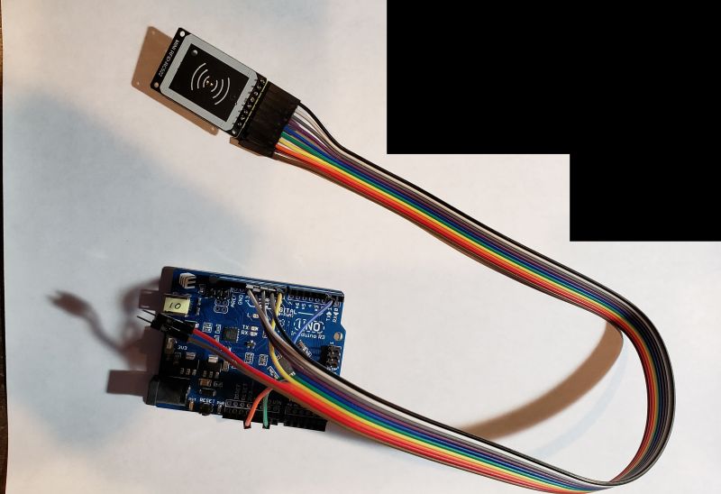
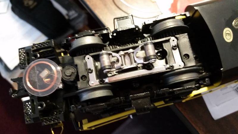
Example of an Arduino with one Tag Reader
Image loading....
Video #2 -
Arduino with One Tag Reader
On this Arduino (video #2),
I've
connected up SCK, MISO and MOSI. SSn/CSn is
connected to pin A5 (Any of 15 pins can be used, I picked this one). 5v
and ground are connected. For an indicator, I used an LED on pin A0.
This LED blinks whenever a tag is detected. Tag is mounted under the
track with antenna side down so that there is no chance of shorting the
antenna to the track. I'll explain about the white wires a later on
this page.
Example of an Arduino with four Tag readers
Image loading....
Video #3 -
Arduino with Four Tag Readers
On this Arduino (video #3), I've connected up SCK, MISO and MOSI to 4
tag readers. (SSn/CSn/SCL) from each tag reader is
connected
to pins A5, 2, A3 and 3 (Any of 15 pins can be used, I picked these).
Power and
ground are connected. For an indicator, I used an LED on pin A0. This
LED blinks whenever a tag is detected. For my testing, I only used 3 of
the readers which you can see placed underneath the track.
Programming the Master Control computer
Now
that I had a method to detect the location of engines and cars on my
layout and a method to control the engines, switch and accessories, I
need a programmatic way to use the engine/car detections to control the
layout.
Now we can
finally implement the functionality of the Lionel 132 Stop Station.
I created three different implentations of this idea. Two are described
on this web page. The third implementation is described here : "RTC
Control Language".
They are:
Version 1. The first version was to use a
Mega 2560 as the Control
Computer. I connected the Infiduino tag detectors to the Mega. I wrote
the code (in C++) for the sketch that runs in the Mega. I used the
serial monitor function of the Arduino IDE to watch what the Mega was
doing as it received tag detections. The Arduino IDE was used to
compile the code and load it into the Mega.. So what you see here are
videos of that implementation.
Version 2. Then I got rid of
the Mega and connected the Infiduino tag detectors directly to the PC
using the USB port. I wrote code (in C++) that ran as part of the RTC
program to process the detected tags. The code became part of the RTC
program and was compiled by the Embarcadero C++ Builder IDE. This was
not very flexible as anyone who wanted to write their own Control
Program had to have the complete C++ development environment installed
on their PC. There are videos of this implementation.
Version 3.
The third and final version was to change the RTC program such that
rather than requiring hard code, RTC instead could run a
scripting
language (I picked Lua) and then it would be easy for anyone to write a
Control Program to operate their layout any way they wanted to. The RTC
program supports 10 Program Control windows that can run at the same
time. The scripting language that I developed is described here : "RTC
Control Language".
So
I really should rewite this section and remove all references to
Version 1 and Version 2 but I think the words and videos are still
instructional so I'm going to leave it for now. Just keep in mind that
if you use this feature, you will only be using step 3.
View the reminder of this web page with these thoughts in mind.
Version 1 Programming an Arduino Mega 2560 to be the Master
Control computer
I used an Arduino
Mega2560 as the Master Control computer (video #4). The Mega
is powered by a 12v wall
wart.
The Mega receives tag detection information from each Arduino over the
hardware serial port #1 ("Serial1"). Almost any kind of program can
be written to act
on tag detection by the Arduino. Command packets can be built and sent
out the radio (see next section) to a TIU to control engines and
accessories.
Step 1 Mega 2560
Image loading....
Video #4 -
Ardino Mega 2560
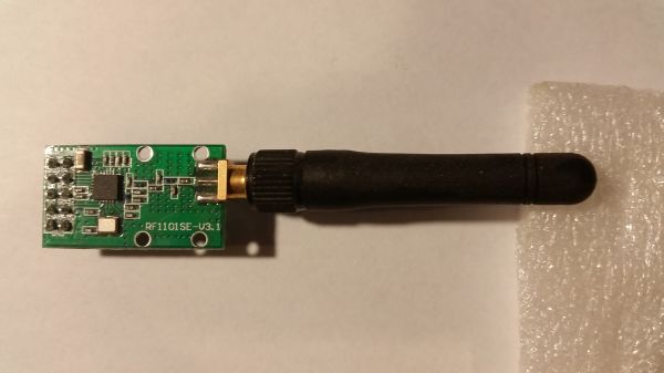
CC1101 Radio by Elechouse
The radio I use is a TI CC1101 based radio from Elechouse.
Note that the image on their web page says RF1100SE but I received the
correct version labeled RF1191SE-V3.1. This is a 3.3V device
and no
signal pin can be connected to a 5V Arduino output.
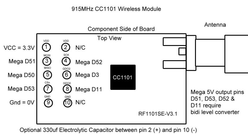
I connected a big (330µf) electrolyitc decoupling capacitor
between VDD
(pin 2) and
GND (pin 10) on the radio board. I don't know if this is really doing
any good or not. You can make it optional.
Be careful when you connect up the radio. This is a TOP VIEW
(or COMPONENT SIDE VIEW) of the board. The pins actually stick out the
back side of the board.
Compiling a sketch which uses the CC1101 radio from Elechouse requires
my library CC1101E. You can download
it from here. In your local Arduino Library folder, create a
folder named "CC1101E"
and put the CC1101E_OOK library files in it.
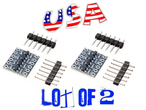
Level shifters
Since the CC1101 radio can only handle 3.3v signals, I used a simple
(and cheap) level convertor. I found these on eBay. These are
bi-directional and can easily handle the SPI command interface to the
radio and speed of data TX/RX to/from the radio (9600 baud).
I level shifted 4 signals: SCK, MOSI, SSn/CSn, and GDO0.
Signals going from the radio to the Mega do not need to be level
shifted, the Mega can correctly read them even as 3.3v signals.
Image from the eBay seller's web page:
Radio and Level Shifter Wiring
On the Mega, I connected
pins from the ICSP connector to the radio.
ICSP 1 - MISO directly to the radio pin 5
ICSP 3 - SCK to a level shifter then to radio pin 4
ICSP 4 - MOSI to a level shifter then to radio pin 3
then
Mega Pin 53 - SSn/CSn to a level shifter then to radio pin 7
Mega Pin 11 - GDO0 to a level shifter then to radio pin 8
Mega Pin 3 - GDO2 directly to radio pin 6
then
3V3 directly to radio pin 1 and the level shifter LV pin
GND directly to radio pin 9 and the level shifter GND pin
5V directly to the level shifter HV pin
Interconnection - Video #5
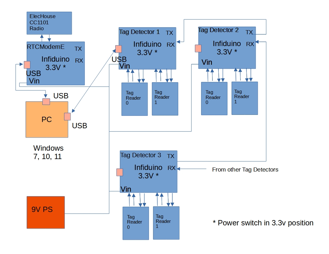
Image loading....
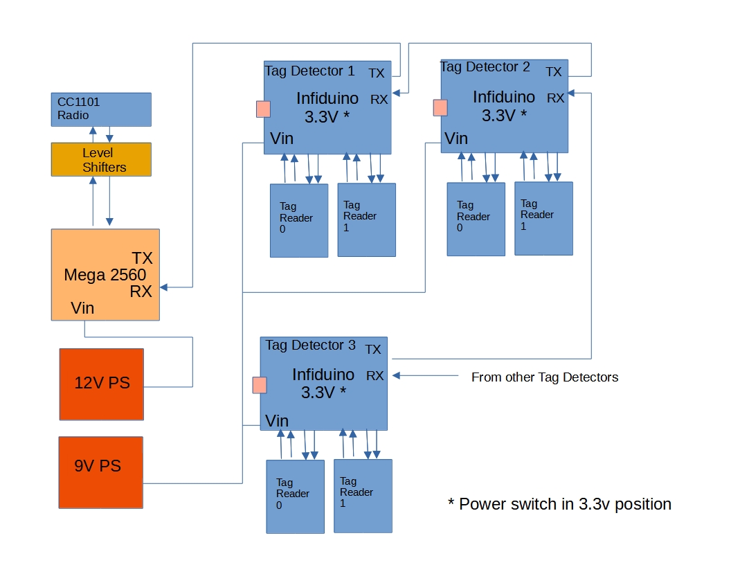
My goal is to have many Arduino around the layout all feeding tag
detections back to a control computer. Each reader
sends out a packet of information when a tag is detected. The hardware
serial TX output of one Arduino is connect to the RX input of the next
Arduino. Each Arduino monitors its RX pin and when a packet
is received, it is forwarded out the TX pin. Eventually the tag
detection information all ends up at the control computer.
This video (#5) shows the interconnection between the Arduinos and the
Mega.
Connecting them is a four wire "telephone" cable. Three wires are used
: 9v raw power (VIN), ground (GND), and serial
data. Each Arduino uses its own voltage
regulator to generate 5v for itself and its associated tag reader
boards. The hardware serial TX pins are not really designed to
send signals
over telephone cable and I'm violating the RS-232 spec here but it
seems
to work. I've got about 10-15 feet of telephone cable between the RX
and TX pins. I'm running the hardware serial lines at 115200 baud.
Then 12v
raw power from a wall
wart is plugged into the Mega.
Here is a simple block diagram of this implementation.
Test run with bells and whistles - Video #6
Image loading....
Video #6 - Test
Run with Bells and Whistles
I wrote a sketch for the Mega (video #6). The sketch receives, on
"RX1" (but on the Mega, labelled "TX1"), the
tag detection information from the two Arduinos. The sketch then uses
the tag information to send commands over the radio to the TIU and
engine. This is a fairly simple sketch that rings
the bell, blows the whistle and adjusts the engine speed. I called the
sketch RTCMegaMaster.
Each time a tag is detected, this sketch receives information about the
engine/car attached to the tag, including:
- Ardino board number 1-XX
- tag reader number 0-14
- 4 byte tag UID
- 16 bytes of engine data which was previously
written into the tag including engine number. Look at
RTC_NFC.h
The video (#8) will describe what action is taken as the
engine
passes over each tag.
More complicated test run with direction changes and
different sounds
Image loading....
Video #7 - Test
Run with Direction Changes
I edited my sketch called RTCMegaMaster
to make it a little more
complicated. I added commands to change the engine direction and play a
few different sounds. The program also is more random at issuing
commands so that it is not just a repeating sequence (video #7).
Of course, this isn't doing anything real world-like.
Unanswered Questions
Since this is a development project, there are still unanswered
questions. I present my list below. Paul Reynolds sent me some
questions about my questions and I added my answers here (Paul's
comments in Red).
1. How reliable will the tag detection be?
> You may need
to employ redundant systems, e.g. RFID and video, or RFID and bar code scanning to get high
reliability.
Right now, the tag is 3 mm above the track, the track is about 10 mm
thick and the antenna is on a 1 mm thick circuit board. So detection
seems good at that 14 mm distance from the antenna
but I don't know the maximum detection distance. Since I plan to put a
tag on every car, I will have to keep that tag as close to the track as
possible.
2. Can an Arduino really handle 6 tag readers?
> Are you
worried about current draw? Too high a workload?
I don't know exactly how the tag readers work so it is probably
possible that if two (or more) tag readers detect a tag at the same
time that the Arduino may not get to the second tag reader before the
second tag leaves the antenna's RF field. (Mark's note: my latest
sketch limits the number of tag readers on each Arduino to 6 -
limited by the number of I/O port pins needed.)
I don't know if the tag reader holds the information untill it is read
out. (Mark's note: later on , I figured out how to make the reader do
this. See below.)
I'm not too worried about current draw. I can always add more 12v
current and use separate 5v regulators for the tag readers (right now,
I use the Arduino to make the 5v for the tag readers (Mark's note: I
have now wired in a separate 9v for the tag
readers).
3. Can the hardware serial interconnection scheme handle the detection
packet traffic?
> Arduinos can
handle software serial as I suspect you know. Why not
use more
than one serial on each Arduino and set up a crude hypercube
>
topology? For a few more ports you can reduce path length,
and thus node
visits, exponentially.
In my scheme, all of the Arduinos are "in series" with respect to the
RS-232 lines. That means the most upstream Arduino is relaying the
packets from all other Arduinos while at the same time handling its own
attached tag readers.
I am using the hardware serial port only and running it at a very high
baud rate (115,200 baud) to try to reduce this problem.
4. Is a Mega powerful enough to work as a control computer or will a PC
program be required?
> Never used a
mega, but I'm not bothered by using a low end PC as the controller.
> You
could use the PC to do other tasks so its capability is not wasted.
I agree, it will probably require a PC.
That brings up the issue of writing a control program that is not
deterministic. We would want a program that simulates an train engineer
in each cab, making decisions on the fly about what to do rather than a
rote step 1, step 2, etc. That is a whole 'nuther can-o-worms.
5. What happens if two tags are detected by two tag readers at
the same time?
> Answer
depends on whether this question pertains to one Arduino with
near simultaneous
inputs, or multiple Arduinos with near simultaneous inputs.
> The latter
shouldn't be a problem. If you're polling the readers from a single Arduino, couldn't you
capture inputs in a time-switched manner?
> Reader
output probably isn't all that fast..
As I mentioned earlier, I am worried about a tag reader never getting a
chance to read out its detection to the Arduino. Right now I poll the
readers one by one. I might be able to change this to a interrupt
driven scheme. Mark's note: I eventually did change to an interrupt
based scheme, see below.
6. What happens if the hardware serial connection is overloaded?
> Not sure
what this question is addressing. Overloaded by
what? Multiple
> concurrent
reader inputs? Multiple comms from other Arduinos?
Both?
The upstream Arduinos might have a lot of RS232 traffic to forward up
to the next Arduino. The hardware serial port can handle fast RS232 but
its buffer could still possibly overflow.
The Arduino Mega2560 has 4 hardware serial ports so I could
make four serial pipelines going into the Mega.
Version 2 Programming a Windows PC to be the Control Computer
Then I got rid of
the Mega and connected the Infiduino tag detectors directly to the PC
using the USB port. I wrote code (in C++) that ran as part of the RTC
program to process the detected tags. The code became part of the RTC
program and was compiled by the Embarcadero C++ Builder IDE. This was
not very flexible as anyone who wanted to write their own Control
Program had to have the complete C++ development environment installed
on their PC. There are videos of this implementation.
Here is a block diagram:
More Testing
5 May 2018 - My first concern is reading the tag information before the
tag moves
off the reader. I wrote a test sketch using the Arduino with 4 tag
readers. The sketch counts the tag detections as the
train goes around the track. It alerts if a tag is missed.
Well, it missed a lot of tags. On each tag, I am trying to:
1. detect the tag (includes 4 byte UID)
2. authenticate the tag key (required as
part of the tag security checking scheme)
3. read up 16 bytes in block 4 which contains
engine data
4. send that information to the Master program
I believe that this is too much to do with the engine running at a
reasonable speed. This works ok if the engine is running at 5-10 Smph
but get into the 20's or higher and the tag moves off of the reader
before all of this work can be completed.
I modified my test sketch so it does:
1. detect the tag (includes 4 byte UID)
2. send that information to the Master program.
This worked much better but can't run more than a few minutes without
missing a tag.
So my first major rewrite of the sketch occurred. Up until
now, the
sketch
polled each reader one at a time to see if a tag was over the reader. I
completely changed that to use interrupts. This required an additional
wire between the reader and the Arduino. For each reader, I connected a
wire between the IRQ pin on the reader and a pin on the Arduino. To
keep the pin usage in check, the new sketch will only support up to 6
readers (I'm still testing with 4). I call the new sketch RTCNFCIRQ.
I made use of
two high speed libraries to try and make the Arduino be as responsive
as possible:
1. Fast Digital
Library
2. High Speed Interrupt Library
Fast Digital Library
This library replaces the digitalWrite() and digitalRead() routines.
You can find the "FastDigital" library here.
This probably only made a small improvement
High Speed Interrupt Library
I used a high speed interrupt library by GreyGnone titled
"EnableInterrupt". You can read about his library here
and here.
I used the very fastest scheme that was supported which required the
statement
#define NEEDFORSPEED
be included in the sketch. This new scheme required one IRQ pin on the
Arduino for each attached tag reader. I decided that one Arduino could
support up to 6 tag readers. Here is how I assigned the pins to
the (SSn/CSn/SCL) and IRQ signals from the 6 tag readers (you
can
use any free
pins on the Arduino):
//------------------------------------------------------------------------------------------
// Each arduino can service up to 6 PN532 readers using both digital
and analog pins for the select - SSn/CSn signal and
// for interrupt - IRQ signal.
// pins 10 - 9 - 8 - 7 - 6 - 5 - 4 - 3 - 2 - A5 - A4
- A3 - A2 - A1
- A0 // 9 digital pins and 6 analog pins work as SSn/CSn and
IRQ
// typically pin 10 is used by the CC1101 radio if that is
used in your implemetation.
// In this sketch, 8 is used for the LED.
//------------------------------------------------------------------------------------------
// Reader Address pins for (SSn/CSn/SCL). Put these in the
order you need based
on your wiring of the PN532 reader boards
uint8_t SSPinAddress[6] = {A0, A1, A2, A3, A4, A5}; //
limited to 6 readers
// Reader Address pins for IRQ
uint8_t INTPinAddress[6] = {2, 3, 4, 5, 6,
7}; // 6 pins for pin
change interrupts
//
uint8_t * int_array[6] = {(uint8_t *)&reader0_pin2, (uint8_t
*)&reader1_pin3, (uint8_t *)&reader2_pin4, (uint8_t
*)&reader3_pin5,
(uint8_t *)&reader4_pin6,
(uint8_t *)&reader5_pin7};
|
This change improved the detection. Instead of polling each reader, the
Arduino just sits in a loop waiting for an interrupt to be signaled by
a reader.
But I think I'm still seeing the case where the tag is detected but by
the time I get to read the 16 bytes of tag block 4 data, the tag has
moved off the reader.
What I needed was a way to have the reader remember the tag UID until I
could get around to reading it. I dug up the manual for the PN532 and
studied the library code. I realized what needed to be done. I had to
write new library routines:
1. enableRead()
- this routine turns on the RF field to power the next
tag. Then when a tag arrives, the reader remembers the tag UID and
sends an
interrupt to the Arduino. Then the Arduino quickly reads up the tag ID
(UID) by calling the next routine.
2. readTargetID()
- this routine just fetches that saved UID.
Right after the next video I show the new routines. This seemed so
simple. but the result was dramatic. Look at this video:
50 Smph with 100% tag detection - Video #8
Image loading....
Video #8 - 100%
Tag Detection
The tag detection looks really good right now (video #8). I had to give
up (at
least for a while) my idea
of keeping engine/car information in 16 bytes of the actual tag. I just
can't read that out when running at speed. I'm thinking, though, that I
can put a reader at the exit/entrance throat of my staging yard, where
trains run fairly slow, and right there, read up the engine/car
information and save it in the Master program. Then on each tag
detection, the Master program can look up the 16 bytes of information. See below where I discovered a
method to really improve the tag detection.
Mark's note: I had also written a third new routine, releaseLastTag().
I never used it but it remains in my copy of the modified files.
PN532.h Patched
|
Here is the top of
the PN532.h file.
The change is exactly the same as described above.
Add the declarations for the three new routines to the "public" section
of the class.
Make the one line change to the beginning and end of the header file.
/**************************************************************************/
/*!
 @file PN532.h
 @author Adafruit Industries & Seeed Studio
 @license BSD
*/
/**************************************************************************/

#ifndef __PN532_H__
#define __PN532_H__

extern unsigned char pn532_packetbuffer[255]; // MCD

#include <stdint.h>
#include "PN532Interface.h"

/**************************************************************************/

// Added by Mark DiVecchio
 bool readTargetID(uint8_t *uid, uint8_t *uidLength, uint16_t timeout = 1000);
 bool deselectLastTag(uint8_t TagNo = 0);
 bool enableRead(uint8_t cardbaudrate);
// MCD

/**************************************************************************/
 uint8_t _felicaIDm[8]; // FeliCa IDm (NFCID2)
 uint8_t _felicaPMm[8]; // FeliCa PMm (PAD)

 //uint8_t pn532_packetbuffer[255]; // MCD

 PN532Interface *_interface;
};

#endif
|
PN532.cpp Patched
|
Here are the new
routines added to the PN532.cpp library code.
/**************************************************************************/
/*!
 Added by Mark DiVecchio to prevent detecting the same tag over and over

 @returns 1 if everything executed properly, 0 for an error
*/
/**************************************************************************/
bool PN532::deselectLastTag(uint8_t TagNo) {
// Deselect the last read tag
byte bTestDeselect[2];
bTestDeselect[0] = PN532_COMMAND_INDESELECT;
bTestDeselect[1] = TagNo; // 0 = all targets (default), 1 = last Target, x = xth to last Target

if (HAL(writeCommand)(bTestDeselect, 2)) {
 return 0x0; // command failed
 }
//
return (0 < HAL(readResponse)(pn532_packetbuffer, sizeof(pn532_packetbuffer)));
}
/**************************************************************************/
/*!
 Enable the reader to send an IRQ when a tag is detected

 @param cardBaudRate Baud rate of the card

 Added by Mark DiVecchio
*/
/**************************************************************************/
bool PN532::enableRead(uint8_t cardbaudrate) {
 pn532_packetbuffer[0] = PN532_COMMAND_INLISTPASSIVETARGET;
 pn532_packetbuffer[1] = 1; // max 1 cards at once
 pn532_packetbuffer[2] = cardbaudrate;

 if (HAL(writeCommand)(pn532_packetbuffer, 3)) {
 return 0x0; // command failed
 }

 return 1;
}
/**************************************************************************/
/*!
 Waits for an ISO14443A target to enter the field

 @param uid Pointer to the array that will be populated
 with the card's UID (up to 7 bytes)
 @param uidLength Pointer to the variable that will hold the
 length of the card's UID.

 @returns 1 if everything executed properly, 0 for an error
*/
/**************************************************************************/
bool PN532::readTargetID(uint8_t *uid, uint8_t *uidLength, uint16_t timeout)
{
 // read data packet
 if (HAL(readResponse)(pn532_packetbuffer, sizeof(pn532_packetbuffer), timeout) < 0) {
 return 0x0;
 }

 /* Card appears to be Mifare Classic */
 *uidLength = pn532_packetbuffer[5];

 for (uint8_t i = 0; i < pn532_packetbuffer[5]; i++) {
 uid[i] = pn532_packetbuffer[6 + i];
 }

 return 1;
}
|
Improved
duplicate tag detection
I rewote the code which filters out multiple detections of a tag as the
tag is passing over a reader. This is a potential problem when the
train is moving slowly over a tag reader. The sketch now remembers the
last tag ID for 750 ms. If that tag ID is detected again within that
time, it is dropped and not sent to the Master control program. The
control program should also implement it's own duplicate tag detection
on top of what I did. (Mark's note: I've had to tune this delay with
the new V4 single board RFID readers from Elechouse. They reacted
differently than the V3 boards. I previously used 500ms but I got a lot
of duplicate tag detections when running slowly over the tag. I
increased the time to 750ms and it seemed to reduce that effect.)
To give you some idea of the transit times involved here - the tag
reader antenna is 1.375 inches across. At 10 Smph, a tag passes over
the tag reader in 375 ms. At 50 Smph, it's 75 ms and at 60 Smph, it's
63 ms. We have to react pretty fast when a tag interrupt occurs. Here
is a table showing those times:
|
|
|
Actual |
Actual |
Tag |
Time under |
Time under |
| Smiles/hr |
Scale |
Sft/sec |
ft/sec |
in/sec |
Length (in) |
Tag (sec) |
Tag (ms) |
|
|
|
|
|
|
|
|
| 10 |
48 |
14.67 |
0.31 |
3.67 |
1.375 |
0.3750 |
375 |
| 20 |
48 |
29.33 |
0.61 |
7.33 |
1.375 |
0.1875 |
188 |
| 30 |
48 |
44.00 |
0.92 |
11.00 |
1.375 |
0.1250 |
125 |
| 40 |
48 |
58.67 |
1.22 |
14.67 |
1.375 |
0.0938 |
94 |
| 50 |
48 |
73.33 |
1.53 |
18.33 |
1.375 |
0.0750 |
75 |
| 60 |
48 |
88.00 |
1.83 |
22.00 |
1.375 |
0.0625 |
63 |
| 70 |
48 |
102.67 |
2.14 |
25.67 |
1.375 |
0.0536 |
54 |
| 80 |
48 |
117.33 |
2.44 |
29.33 |
1.375 |
0.0469 |
47 |
Increasing the
size of the hardware serial RX and TX buffers
I increased the size of the buffers used by the hardware serial ports
on the Arduino and the Mega2560. In the Arduino IDE folders, there is a
file named "boards.txt". This file contains definitions of all of the
boards understood by the IDE. I took the "Arduino/Genuino" and "Mega
2560" entries, copied and renamed them, and added two options to the
build line. These options
increase the RX and TX buffers to 256 bytes.
I changed the names to "Uno Big RX/TX Buffer" using "unoB" and "Mega
2560 Big RX/TX
Buffer" using megaB. You should select one of these on the
Tools->Board menu
of
the IDE.
I'm not sure that this change is necessary but I thought I should use
the biggest reasonable buffer sizes to minimize possible buffer
overflow on the serial connections.
The original Arduino/Genuino and Mega 2560 boards can still be selected
for other projects. This method of making the change means we don't
have to modify the library HardwareSerial.h source code (the support
for these two flags is already built into Hardware Serial.h so no
changes are needed to library files).
|
Add these lines to
the boards.txt file
##############################################################

unoB.name=Uno Big RX/TX Buffer

unoB.vid.0=0x2341
unoB.pid.0=0x0043
unoB.vid.1=0x2341
unoB.pid.1=0x0001
unoB.vid.2=0x2A03
unoB.pid.2=0x0043
unoB.vid.3=0x2341
unoB.pid.3=0x0243

unoB.upload.tool=avrdude
unoB.upload.protocol=arduino
unoB.upload.maximum_size=32256
unoB.upload.maximum_data_size=2048
unoB.upload.speed=115200

unoB.bootloader.tool=avrdude
unoB.bootloader.low_fuses=0xFF
unoB.bootloader.high_fuses=0xDE
unoB.bootloader.extended_fuses=0x05
unoB.bootloader.unlock_bits=0x3F
unoB.bootloader.lock_bits=0x0F
unoB.bootloader.file=optiboot/optiboot_atmega328.hex

unoB.build.mcu=atmega328p
unoB.build.f_cpu=16000000L
unoB.build.board=AVR_UNO
unoB.build.core=arduino
unoB.build.variant=standard
unoB.build.extra_flags=-DSERIAL_RX_BUFFER_SIZE=256 -DSERIAL_TX_BUFFER_SIZE=256

##############################################################
##############################################################

megaB.name=Mega 2560 Big RX/TX Buffer

megaB.vid.0=0x2341
megaB.pid.0=0x0010
megaB.vid.1=0x2341
megaB.pid.1=0x0042
megaB.vid.2=0x2A03
megaB.pid.2=0x0010
megaB.vid.3=0x2A03
megaB.pid.3=0x0042
megaB.vid.4=0x2341
megaB.pid.4=0x0210
megaB.vid.5=0x2341
megaB.pid.5=0x0242

megaB.upload.tool=avrdude
megaB.upload.maximum_data_size=8192

megaB.bootloader.tool=avrdude
megaB.bootloader.low_fuses=0xFF
megaB.bootloader.unlock_bits=0x3F
megaB.bootloader.lock_bits=0x0F

megaB.build.f_cpu=16000000L
megaB.build.core=arduino
megaB.build.variant=mega
# default board may be overridden by the cpu menu
megaB.build.board=AVR_MEGA2560
megaB.build.extra_flags=-DSERIAL_RX_BUFFER_SIZE=256 -DSERIAL_TX_BUFFER_SIZE=256

## Arduino/Genuino Mega w/ ATmega2560
## -------------------------
megaB.menu.cpu.atmega2560=ATmega2560 (Mega 2560)

megaB.menu.cpu.atmega2560.upload.protocol=wiring
megaB.menu.cpu.atmega2560.upload.maximum_size=253952
megaB.menu.cpu.atmega2560.upload.speed=115200

megaB.menu.cpu.atmega2560.bootloader.high_fuses=0xD8
megaB.menu.cpu.atmega2560.bootloader.extended_fuses=0xFD
megaB.menu.cpu.atmega2560.bootloader.file=stk500v2/stk500boot_v2_mega2560.hex

megaB.menu.cpu.atmega2560.build.mcu=atmega2560
megaB.menu.cpu.atmega2560.build.board=AVR_MEGA2560

## Arduino Mega w/ ATmega1280
## -------------------------
megaB.menu.cpu.atmega1280=ATmega1280

megaB.menu.cpu.atmega1280.upload.protocol=arduino
megaB.menu.cpu.atmega1280.upload.maximum_size=126976
megaB.menu.cpu.atmega1280.upload.speed=57600

megaB.menu.cpu.atmega1280.bootloader.high_fuses=0xDA
megaB.menu.cpu.atmega1280.bootloader.extended_fuses=0xF5
megaB.menu.cpu.atmega1280.bootloader.file=atmega/ATmegaBOOT_168_atmega1280.hex

megaB.menu.cpu.atmega1280.build.mcu=atmega1280
megaB.menu.cpu.atmega1280.build.board=AVR_MEGA

##############################################################
|
But the verdict on this change is still not in. I'm not sure it makes
any
difference.
Getting
to 100% tag detection with read up of 16 bytes of data - Video #9
So tag detection was working really well as long I only read the Tag ID
(UID 4 bytes) on each detection. My original plan was to encode 16
bytes of
information in each tag that described the engine/car. The contents of
these 16 bytes is described in the struct "ED" as shown in RTC_NFC.h.
I enabled that part of the code by setting SENDENGINEDATA to true. I
got my short train running around the circle. I was still missing
detection of about 10% of tags - not a good percentage when the engine
is about to run off the edge of the layout. I experimented with
changing
the code and repositioning the tags under the track. Nothing
made any
difference.
As I was narrowing down my problem with unreliable train detection, I
was thinking that an Arduino with 4 tag readers might be pushing the
power supply current limit as the RF field is turned off and on. This
could cause a voltage drop which
could make the tag reader less sensitive. And I realized that the
Arduino with one tag reader was getting 100% tag detection and 16 byte
engine data readout.
I said "what I need is a
good decoupling capacitor" across the 12 volt
power supply. I found a 220µf 16v capacitor and jumpered it
across the
12 volt (VIN) pin and GND. I saw a good improvement. Then I said, maybe
a capacitor
across the 5 volt output of the voltage regulator would help more. So I
unpluged the capacitor, moved the jumper to the 5 volt pin on the
Arduino and connected the capacitor across the 5 volt pin and GND.......
Gee those LED's
on the boards flashed bright!
Death! In my unthinking, I placed a fully charged up (to 12 volts)
capacitor across the 5 volt supply and quietly burned out an Arduino
and 4 tag readers. It took me a while to figure out what happened and
in my testing, I burned out another Arduino. To wit:
Detritus
So it took me several hours to reassemble (slowly and step by step)
another Arduino and 4 new tag readers. I took great care to connect the
decoupling capacitor across only the 12v power supply. At the same
time, to ensure enough current to the readers, I powered this Arduino
with a separate
12VDC wall wart power supply.
Mark's
note: Now I'm just powering the Arduino and tag reader with a big 5v DC
power supply. I connect the 5v to the VIN pin on the Arduino and the
VCC pin on the reader (each reader has a voltage regulator to create
3.3v needed there).
The good news is
that the tag detection is working really well now.
I've been running a four tag train (running at 40 Smph) over 4
detectors for about an hour and and its been 100% success.
My program is detecting the tag, authenicating the security key and
reading up 16 bytes of engine/car data on each detection. The 16 bytes
contains the type of engine/car, its car number and railroad as defined
in RTC_NFC.h. This
requires 3 RF interactons between the tag reader and the tag as the
train is speeding along the track. More testing showed that I could run
up to 50 Smph and still read up the 16 bytes. (When I tried to
read up the tag ID (UID) only, I could get up to 60-70 Smph.)
Remember at 50 Smph, the tag is over the reader for only 75 ms.
Here is a video (#9):
Image loading....
Video #9 - Tag
Detection Success
Straight Track
with Siding Demo - Video #10
A more complicated demo that starts to show how this tag detection
system along with a radio could be used to control a layout.
Probably best to look at the video (#10) and then read a detailed
description
below:
Image loading....
Video #10 -
Straight Track With Siding Demo
The Arduinos with the tag readers are running my RTCNFCIRQ program.
They monitor the tag readers and when a tag is detected, they
read the 16 byte engine/car description and the tag ID (UID)
from the tag. That information is packaged up and sent out the serial
port to the Master Control sketch.
The Mega2560 is in overall control of the layout. The sketch (RTCMegaMaster) in
that computer starts up the engine at the beginning of the run and
then receives the tag information from all of the readers on
the layout and acts on that information. The Master Conrol sketch
creates correctly formated commands which are sent to the CC1101E radio
attached to it. Those commands are then passed on by the TIU to the
engines on the track.
The demo uses an AIU to control two 022 switch tracks and a 145 Gateman.
Once the engine is started in the forward direction at 11 Smph, the
sketch waits for a tag detection from any of the tag readers. All of
this action is coded in the sketch running on the Mega (this can all be
done on a PC also).
The first tag that the control sketch cares about is the tag on the
caboose. The 16 bytes of information read up by the tag reader contains
data which identifies that car as a caboose and includes the car
number. Once that tag is detected, the sketch builds commands for the
TIU that stop the engine, reverse direction, throw the switch tracks
and start the engine moving.
The engine travels over the layout until, at the other end, the tag on
the front truck of the engine is detected. When that occurs, the
control sketch stops the engine, reverses direction, throws the
switches and starts the engine in the forward direction. This time, the
engine takes the siding.
The Gateman is controlled by the control sketch also but the sketch is
programmed to wait 15 seconds before commanding him to pop out.
Actually any command can be delayed by any number of seconds for
actions that have to happen some time after a tag detection. I use this
method when an engine begins to move to sound the bell and 2-3 toots on
the horn.
Uncoupling on
the Siding Demo - Videos #11 & #12
Another more complicated demo that starts to meet my goal of running a
layout.
Look at the video (#11) and then read a detailed description
below:
Image loading....
Video #11 -
Uncoupling Demo - Part I
Remember that this is all being controled by the Master sketch running
on the Arduino Mega 2650.
So this demo swaps the two cars around. The demo can run over and over,
each time doing the swap.
Coupling and uncoupling was the hardest part of this demo. When
coupling, you have to have Charlton Heston's help and be running at
"Ramming Speed". In my demo, that meant the engine had to be going
about 20 Smph. Not very realistic. This was a real issue as many
boxcars and gondonlas are too light. When you push against their
coupler with an engine coupler, rather than holding firm and letting
the coupler couple, they tend to just get pushed down the track. I
found that the green boxcar that I used weighed 12 oz. According to the
NMRA, a 10 inch O scale car should weight 5 oz plus 1 oz for each inch
of length - or in this case - 15 oz. It made a little difference when I
added 3 oz of lead weights to the car. But with these Delrin journals
and fast angles wheel sets, the cars don't put up much resistance. In
my demo, I try to couple onto one car - a consist of 3-4 cars would
offer more resistance. The 8 inch long caboose was already pretty heavy
at 18 oz.
Uncoupling was a problem also. I found that the engine had to be moving
at the instant the uncouple command was executed so that the engine
would pull away from the car. I also tried uncoupling on the fly to add
some interest - that worked pretty well.
Here is the engine swapping the cars back to where they started (video
#12):
Image loading....
Video #12 -
Uncoupling Demo - Part II
Looping
Demo -
Videos #13, 14 and 15
December 2018
With some improvements to the RTC program (used as the Master Control
program) and small changes to the train detection and control scheme in
the RTC program, I have a looping demo running on my carpet test track.
My goal has always been to increase the reliability of the train
detection to as close to 100% as possible.
Changes to the RTC program.
One the RTC
program web page, you can read about the changes that I made
to the communications code in version 3.27 of that program. These were
some major changes and made the communications between the program and
the TIU/engine much more reliable.
Changes to the train detection scheme
1. I had always planned to put two tags on each engine, one at each
end. The intent was to be able to determine the direction (forward or
reverse) an engine
was moving when it passed over a detector. Since I had two tags, I
changed the train detection to watch out for both tags. If it missed
one, it might detect the other one.
2. For each tag detected, I save the UID & block 4 (engine
data) in a lookup table. In my earlier testing that you can read about
above, I've often seen a failure where the tag passes over the reader
too quickly for the block 4 data to be read out. So when I start the
demo, I run the engines slowly at first and as each tag is detected, I
add that tag and block 4 data to a list. Then later, when running at
higher speeds, if the detector can't read the block 4 data but gets the
tag UID, I lookup that UID in the list and use the previously read up
block 4 data.
Changes to the train control scheme
On the advice of Mike Hewett, I send all of the critical commands
twice. Even if the TIU responds that the command was successful, I
still send the command again. This is
most useful for the speed & direction commands. It is
absolutely critical that the engine go at the speed required and in the
direction required. I also do this for bell off and horn/whistle off
because its annoying if they don't turn off.
This might be overkill.
The Videos
Here are three videos of my loop demo. The first describes and shows
the
operation of the engines on the test track. The second shows that PC
screen when the RTC program is controlling the engines. The third is
after I moved the RFID detectors to my layout in the train room. That's
me
narrating the videos.
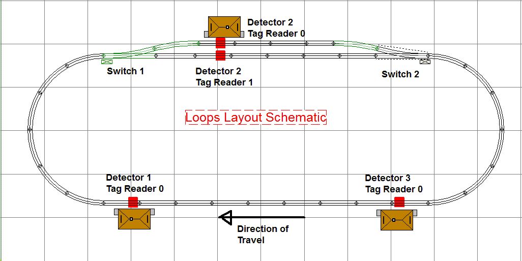
Here is a schematic of the layout. The RFID tag readers are shown in RED. There are 3
Arduino detectors, two with a single RFID tag reader and one with two
RFID tag readers.
Image loading....
.
.
.
.
Image loading....
Image loading....
Video #15 -
Loop Demo - Part III - Running on my train room layout
Higher res version on YouTube: https://www.youtube.com/watch?v=XanTORsiyiQ
Version 3 RTC
Control Language
As Mike Hewett pointed out,
one of the limitations of the version 2 "Program
Control" ability of RTC is that you have to know how to program in C++
and
have the complete RTC development environment on your computer.
Look at
this
page for my solution.
Program summary and
source code
I'll
try to keep these zip files up to date but if you are going to
seriously work with them, email me to be sure you have the latest
versions.
RTCNFCIRQ
This
is the new sketch using high speed interrupts and the FastDigital
library
.
Download here.
RTCNFCProg
I took the tag writing code
out of each sketch and made up a new sketch
called RTCNFCProg. Use this sketch to program the 16 bytes of
engine/car information into Block 4 of the tag.
Download here.
Not useful any more - superceded
by the "Tag Programmer" program.
Tag
Programmer
This is the program to
run on your PC used to program tags. Requires an Arduino programmed
with the latest RTCNFCIRQ sketch. If you need this program now, email
me. I'll have it posted here soon.
RTC_NFC
Library
You will need the RTC_NFC.h
header file from the RTC_NFC library.
Download
here.
PN532 Library as
Patched
The original library with
the new routines in PN532.cpp and PN532.h. These files are in the
folder named PN532_modified.
Download here.
This site prepared and maintained by Mark
DiVecchio
email : markd@silogic.com
SD&A
HOME
Mark's Home Page
The DiVecchio
genealogy home page
The Frazzini
genealogy home page
This site will be under construction for a while.