Mark DiVecchio's O-Gauge Train Layouts

1992 Layout Page

2006 Layout Page

2009 Layout Page

P&LE Postcards by Howard Fogg 

Plasticville Buildings

Portable Layout Page

Train Clubs

Bing Track

Remote Train Control Program

YouTube Channel

OOK Radio Support

Technical Videos

3D Prints for my Layout

More RTC Videos

ADPCM - Playing clips from .mth sound files

P&LE McKees Rocks Locomotive Shop
3D Printer Project

White Tower Restaurant
3D Printer Project

RFID Train Detection

Engine and Car Operation
Hints and Tricks

RFID Tag Programmer using PN532

RTC Control Language - Scripting

RTCAdapter  ESP8266 Sketch

More RFID Tag Videos

RTC Control Language - Signaling

Signals


RTC Signal

This Page last updated on .

I started development of this web page in December 2025. It will be under construction for a while.

On this page, I describe the ESP8266 code for  RTCSignal - a sketch that lets you control two of Mike Hewett's 3D printed 3 head signals. RTC will support up to 100 ESP8266 each of which can control 2 signal heads for a total of 200 signals.

For a complete description of the Signalling system supported by RTC, click here .

Click here for the copyright notice.

 Background

I've been working on ways to control my MTH trains from my PC for many years. About 8 years ago, I released the first version of my Remote Train Control (RTC) program for the PC. The very first version was for a TIU tethered between the Remote jack on the TIU to a serial port on the PC (or a USB serial port). Next came a radio which enables RTC communicate to over a wireless radio connection to a TIU. After that came the ability for RTC to communicate over WiFi with both the WIU/TIU and the WTIU.

I've written several utility sketches to help me learn and understand how the trains are controlled. For example:
With a lot of effort, I was able to understand almost all of the communications between the Remote and TIU. I am now able to create packets to control the engines. The packets are complete with correct addressing, command syntax and CRC.

I figured this out by examination of the packets that I could sniff using Mike Hewett's original RS-232 interface design and the port settings that he found. Without Mike's insights into the RS-232 data stream, I don't think that I would have been able to get a foothold into this protocol.

So again, I figured this out just by looking at the RS-232 stream over the tether cable. No code disassembly, no logic analyzers, no opening up of Remotes or TIU's.

The sketches originally used USB based serial communications to the RTC program using the Infiduino. Then they moved to the ESP8266 using WiFi commications with the RTC program.
Now I've written an ESP8266 sketch that lets you control 2 of Mike Hewett's 3D printer 3 head signals. This sketch can be controlled by the RTC program.

This description is in three sections:
    Section 1 : The 3 head signals are described  on a separate web page. Click Here.
    Section 2 : The ESP8266 program which controls the signals is described on this web page
    Section 3 : The RTC program written in lua which sends the commands to the ESP8266 to control the signals is described  on a separate web page. Click Here.

Section 2 :The ESP8266 Program Which Controls the Signals

Mike Hewett always seems to be acknowledged on my web pages and he deserves it. Mike learned about the ESP8266 based NodeMCU board and started to use it in his projects. After I saw his success and how easy it was to use, I started to rewrite my TIU Emulator (RTCEngine) sketch to use that device.

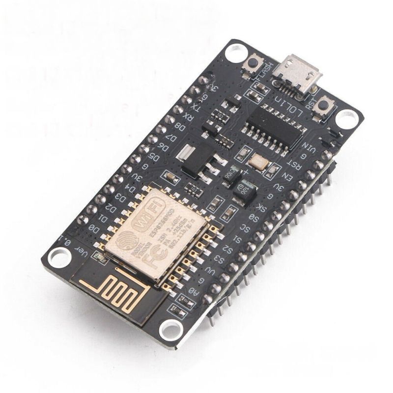
The ESP8266 is a small powerful computer connected to a WiFi Radio. They are available from many sources on the Internet. Watch out for knock-offs.


My Ideas

Here is a photo of an ESP8266. I've been using the LoLin version with the CH340 USB chip and one built-in LED on D4. Note that the CH340 chip (SOP-16 chip near the USB connector) is unlabled - probably a clone. Bought on eBay. Along with two of Mike's 3D printed signal is all that is needed for the RTCSignal sketch. Read below about the CH340 driver issues with the unlabeled chip in Windows.

NOTE: After all the trouble I had with the unlabeled CH340 USB chip, I no longer recommend the version of the ESP8266 with the unlabeled device. Apparently the unlabeled CH340 is a clone that does not work with the latest original CH340 drivers (which do work with the original CH340). Either find an ESP8266 with a labeled CH340 or use the ESP8266 with the CP2102 USB chip.


Below is a photo of another ESP8266. It is the AITRIP or HiLetgo version with the Silicon Labs CP2102 USB chip and one built-in LED on D4. Note that the CP2102 chip (28 pin QFP SMD chip near the USB connector) is labeled. Bought on Amazon.

NOTE: After all the trouble I had with the unlabeled CH340 USB chip, I no longer recommend the version of the ESP8266 with the unlabeled device. Apparently the unlabeled CH340 is a clone that does not work with the latest original CH340 drivers (which do work with the original CH340). Either find an ESP8266 with a labeled CH340 or use the ESP8266 with the CP2102 USB chip.


The ESP8266 that I have all have the LED on pin D4. Some versions of the ESP8266 have the LED on pin D0. This can be powered bay 4-AA batteries, with a USB cable plugged into a USB port (on your computer), directly from a 5 volt wall wart or from one of the many buck converters that geneate 5.0 or 3.3 VDC. 


Parts Sources

Three sources for the ESP8266:

NOTE: After all the trouble I had with the unlabeled CH340 USB chip, I no longer recommend the version of the ESP8266 with the unlabeled device. Apparently the unlabeled CH340 is a clone that does not work with the latest original CH340 drivers (which do work with the original CH340). Either find an ESP8266 with a labeled CH340 or use the ESP8266 with the CP2102 USB chip.

ESP8266 NodeMCU CP2102 ESP-12E Internet WiFi Development Board      https://www.amazon.com

NodeMcu Lua ESP8266 CH340G ESP-12E Wireless WIFI Internet Development Board:  https://www.ebay.com

NodeMCU ESP8266 ESP-12 WiFi Development Board Module ESP 8266 ESP8266MOD w/CH340:  https://www.ebay.com


Image loading....


TBD


RTC Signal (sketch in file RTCSignal.ino)
This sketch is similar to the original Radio based RTC TIU Emulator (RTCEngine) except all communications is done over WiFi. This sketch does not need a radio - All communication is over WiFi which is built into the ESP8266 board.

During the setup as shown below, you set the numbers of the two signals which this ESP8266 can control..

The sketch named "RTCSignal.ino" compiles into one runtime module which can be uploaded into the ESP8266. At the bottom of this page are instructions for loading a precompiled binary into an ESP8266 and instructions for compiling the source code yourself.

There is some debug output that the sketch sends out the USB port. You can use a terminal emulator (I like 'Termite") set at 115200 baud to watch this debug output.

WiFi Setup

When you first load the ESP8266 with the compiled sketch, it must connect up to the WiFi router (so we need the SSID of the router and the password) and you must tell it the WTIU number and the engine number.

The first time it runs, it will automatically connect in this "setup" mode. After that, it will reenter "setup" if the SSID router is not found or if you perform two presses of the ESP8266 reset button [RST] a few seconds apart.

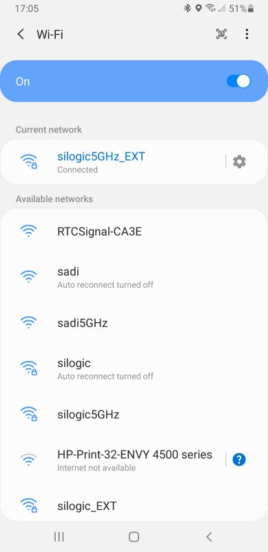
"Setup" is performed by connecting to the ESP8266 from your phone or a WiFi enabled computer. Tap on your WiFi icon and follow along (using the cell phone as the example):

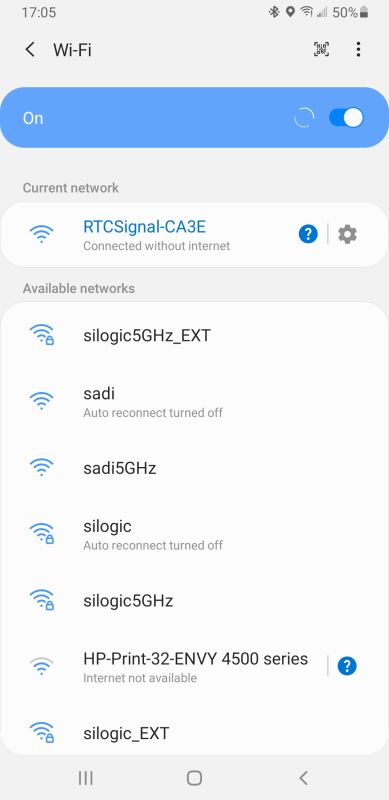
After you upload the RTCSignal sketch into the ESP8266, it will start an Access Point. If you look on your phone, you will see the new WiFi AP listed as "RTCSignal_XXXX".

Touch on that AP to connect to it.

 The phone should connect up and you should see "RTCSignal-XXXX Connected without internet".

If your phone can't seem to maintain the network connection, look for a prompt asking if you want to stay connected even though an internet connection is not available. When you get that prompt, press "Stay Connected".


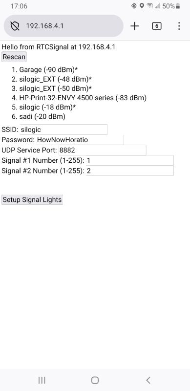
. Then startup a web browser. Enter this IP address into the Address Bar:  192.168.4.1 . Press GO. You should see this screen which lists all of the accessibleWiFi routers in the area. Here is were we enter the information that the RTCSignal sketch needs to communicate with your computer via the WiFi router.

Enter:
The SSID of your router
The WiFi password of your router
The UDP Service Port - don't change this.
The first (odd) signal number.
The second (even) signal number.

Then click on [Setup Signal Lights].
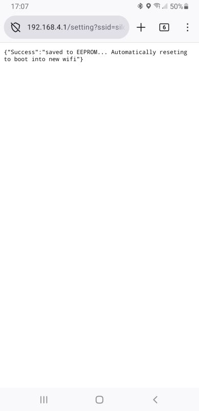
You should see this screen indicating that the device is rebooting and will connect up the WiFi Router.

The ESP8266 will reboot and start. If the LED on the board stays on, the board is having trouble connecting to the router.

If you need to change these setting after first setting them, press the ESP8266 reset button twice a few seconds apart. The ESP8266 will then let you go through these setup steps again.

The ESP8266 will reboot.

The sketch first tries to connect to the router. The LED on the ESP8266 will stay solid blue until it does that. If the LED stays on solid, it indicates the sketch can't connect to the WiFi router. Probably the wrong SSID and/or password were entered.

Once everything is running, the LED will blink each time the sketch responds to a command from RTC.

Getting the sketches into an ESP8266

There are two ways to get the program installed into the ESP8266

1. Use the pre-compiled binary file that I supply and upload it into the ESP8266 using a COMx port.

2. Use the pre-compiled binary file and I supply and upload it into the ESP8266 using the HTTPUpdater and a browser (like Firefox or Chrome). This requires that you do the very first upload using a COMx port.

3. Install the complete Arduino/ESP8266 development environment (IDE), compile the sketch yourself and load it into the ESP8266 using a COMx port

4. Using the Arduino/ESP8266 IDE, compile the sketch yourself and load it into the ESP8266 using the OTA (Over the Air) technique. This requires that you do the very first upload using a COMx port.

Here are (probably incomplete) instructions for each method.

RTCSignal : loading compiled code using RTCSignal-X.XX.zip and COMx port

RTCSignal            This is an ESP8266 NodeMCU based sketch using WiFi  only

If you want to work with this, contact me for the zip file. I will have it on-line once it is stable.

1. install Python 3.12 from:

https://www.python.org/downloads/release/python-3128/

I used the "Windows installer (64-bit)". Some users have reported that they had to check the box  "[X] Use admin privileges when installing py.exe" in order for the "upload.bat" file to execute correctly.


Image loading....


Installing Python


2. Make a folder somewhere

3. unzip the RTCSignal-X.XX.zip file into that folder

4. connect your ESP8266/CC1101E to a USB port. You will need to know the COMx port that Windows assigns to the ESP8266. You can use the "Device Manager" to get that. Search for that program and run it. Click on "Ports (COM & LPT)" and note the COMx port assigned.

5. It appears that some (maybe all) ESP8266 are not supported by the default WIN10 and WIN11 CH340 driver. If you get a permission error on the COMx port when uploading, you will have to replace the current CH340 driver with an older version. On my computer, I replaced the current version 3.9.2024.9 with version 3.5.2019.1. I've run the following steps on both WIN10 and WIN11 machines:

    a. Go to the folder "CH340" which was installed as part of the main RTCSignal-X.XX.ZIP.
    b. Double click on "setup.exe". Click the [Yes] button at the UAC prompt.
    c. Click on [INSTALL] (for version 3.5.2019.1) and in a minute or so, you should see the "Driver install success!" message.

    You can look at the version of the driver installed by right clicking on "My Computer->Manage->Device Manager->Ports (COM & LPT)->Properties->Driver".
    If you ever need to return to the default CH340 driver, on the Properties window in Device Manager, click on [Update Driver].
    I found that Windows kept on updating the driver automatically. Click here for a Registry edit that should prevent this.

5a. Other versions of the ESP8266 use the Silicon Labs CP2102 USB chip. This version of the board seems to work better with the default Windows drivers. If the default Windows drivers don't get loaded, you can download the "CP2102 Universal Windows Driver" from the Silicon Labs web site. Unzip the file, right click on "silabser.inf" and select "Install"

6. edit the file "upload.bat" with notepad

    edit the port number for the USB port connected to the ESP8266

    change "COM4" to the USB serial port.

    save the file

6. double click on "upload.bat" and the upload into the ESP8266 should occur.

Image loading....

Loading Compiled Binary into the ESP8266 (this is for RTCAdapter but it should look very similar for the RTCSignal)


7. Here is a transcript of a successful upload:

E:\Projects\ESP8266\RTCRemote>rem

E:\Projects\ESP8266\
RTCRemote>rem USB

E:\Projects\ESP8266\
RTCRemote>"C:\Users\markd\AppData\Local\Programs\Python\Python312\python" -I "upload.py" --chip esp8266 --port "COM4" --baud "115200" ""  --before default_reset --after hard_reset write_flash 0x0 "build\esp8266.esp8266.nodemcuv2/RTCRemote.ino.bin"
esptool.py v3.0
Serial port COM4
Connecting....
Chip is ESP8266EX
Features: WiFi
Crystal is 26MHz
MAC: ac:0b:fb:ce:d6:2a
Uploading stub...
Running stub...
Stub running...
Configuring flash size...
Auto-detected Flash size: 4MB
Compressed 367792 bytes to 261823...
Wrote 367792 bytes (261823 compressed) at 0x00000000 in 23.1 seconds (effective 127.3 kbit/s)...
Hash of data verified.

Leaving...
Hard resetting via RTS pin...

E:\Projects\ESP8266\
RTCRemote>rem

E:\Projects\ESP8266\
RTCRemote>pause
Press any key to continue . . .


Then follow the instructions above to enter the SSID and password of your router into the ESP8266.


2. RTCSignal : loading pre-compiled binary code using RTCSignal-X.XX.zip and the HTTPUpdater (with a browser like Firefox or Chrome)

RTCSignal            This is an ESP8266 NodeMCU based sketch using WiFi  only

If you want to work with this, contact me for the zip file. I will have it on-line once it is stable.

You must have used method 1 or 3 at first to upload the pre-compiled binary, then further uploads can use this method.

1. Open "http://RTCSignal-XXXX.local:8881/update" in your browser - replace XXXX with the four hexidecimal digits of your ESP8266.

2. Just click [Browse...] to select the "Firmware" file at ".\build\esp8266.esp8266.nodemcuv2\RTCSignal.ino.bin"

3. Press [Update Firmware]. The "FileSystem" update is not used.

3. RTCSignal : compiling source code using RTCSignal-X.XX.zip and a COMx port.

RTCSignal            This is an ESP8266 NodeMCU based sketch using WiFi  only

If you want to work with this, contact me for the zip file. I will have it on-line once it is stable.

To compile these, I used the Arduino IDE version 2.3.4. You will have to download the IDE, install it and then install the ESP8266 board.

1. Make a folder somewhere

2. unzip the RTCSignal-X.XX.zip file into that folder

3. connect your ESP8266/CC1101E to a USB port

4. It appears that some (maybe all) ESP8266 are not supported by the default WIN10 and WIN11 CH340 driver. If you get a permission error on the COMx port when uploading, you will have to replace the current CH340 driver with an older version. On my computer, I replaced the current version 3.9.2024.9 with version 3.5.2019.1. I've run the following steps on both WIN10 and WIN11 machines:

    a. Go to the folder "CH340" which was installed as part of the main RTCSignal-X.XX.ZIP.
    b. Double click on "setup.exe". Click the [Yes] button at the UAC prompt.
    c. Click on [INSTALL] (for version 3.5.2019.1) and in a minute or so, you should see the "Driver install success!" message.

    You can look at the version of the driver installed by right clicking on "My Computer->Manage->Device Manager->Ports (COM & LPT)->Properties->Driver".
    If you ever need to return to the default CH340 driver, on the Properties window in Device Manager, click on [Update Driver].
    I found that Windows kept on updating the driver automatically. Click here for a Registry edit that should prevent this.

4a. Other versions of the ESP8266 use the Silicon Labs CP2102 USB chip. This version of the board seems to work better with the default Windows drivers. If the default Windows drivers don't get loaded, you can download the "CP2102 Universal Windows Driver" from the Silicon Labs web site. Unzip the file, right click on "silabser.inf" and select "Install"

5. Download and install the IDE from the Arduino download page.

    Click on menu item  "Tools->Board->Boards Manager", select "esp8266 Community version 3.1.2" and click on [Install]. There may be a newer version.

    Before compiling, use the "Tools->Board->esp8266" menu to select board "NodeMCU 1.0 (ESP-12E Module)".

    From the Arduino IDE, use the "Sketch->Include Library->Manage Libraries", find these library and click [Install]. There may be a newer versions.
   
ESP_DoubleReset_Detector v1.3.2 by Khoi Hoang
ESP8266TimerInterrupt v1.6.0 by Khoi Hoang
  
    Press the [Verify] button on the Arduino IDE. It should be error free and if you set the IDE preference for verbose output during compile, you should see these libraries being used (they might not be in the same folders on your computer):

Using library ESP8266WiFi at version 1.0 in folder: C:\Users\markd\AppData\Local\Arduino15\packages\esp8266\hardware\esp8266\3.1.2\libraries\ESP8266WiFi
Using library ESP8266HTTPClient at version 1.2 in folder: C:\Users\markd\AppData\Local\Arduino15\packages\esp8266\hardware\esp8266\3.1.2\libraries\ESP8266HTTPClient
Using library ESP8266WebServer at version 1.0 in folder: C:\Users\markd\AppData\Local\Arduino15\packages\esp8266\hardware\esp8266\3.1.2\libraries\ESP8266WebServer
Using library ArduinoOTA at version 1.0 in folder: C:\Users\markd\AppData\Local\Arduino15\packages\esp8266\hardware\esp8266\3.1.2\libraries\ArduinoOTA
Using library ESP8266mDNS at version 1.2 in folder: C:\Users\markd\AppData\Local\Arduino15\packages\esp8266\hardware\esp8266\3.1.2\libraries\ESP8266mDNS
Using library EEPROM at version 1.0 in folder: C:\Users\markd\AppData\Local\Arduino15\packages\esp8266\hardware\esp8266\3.1.2\libraries\EEPROM
Using library ESP8266HTTPUpdateServer at version 1.0 in folder: C:\Users\markd\AppData\Local\Arduino15\packages\esp8266\hardware\esp8266\3.1.2\libraries\ESP8266HTTPUpdateServer
Using library ESP_DoubleResetDetector at version 1.3.2 in folder: C:\Users\markd\Documents\Arduino\libraries\ESP_DoubleResetDetector
Using library LittleFS at version 0.1.0 in folder: C:\Users\markd\AppData\Local\Arduino15\packages\esp8266\hardware\esp8266\3.1.2\libraries\LittleFS
Using library ESP8266TimerInterrupt at version 1.6.0 in folder: C:\Users\markd\Documents\Arduino\libraries\ESP8266TimerInterrupt
Using library EspSoftwareSerial at version 8.0.1 in folder: C:\Users\markd\AppData\Local\Arduino15\packages\esp8266\hardware\esp8266\3.1.2\libraries\SoftwareSerial


6. Before uploading the compiled sketch into the ESP8266, from the "Tools->Port" menu to select the USB COMx port connected to the ESP8266.

7. Then press [Upload] on the Arduino IDE.

Then follow the instructions above to enter the SSID and password of your router into the ESP8266.


4. RTCSignal  : compiling source code using RTCSignal-X.XX.zip and use the OTA (Over the Air) upload.

RTCSignal          This is an ESP8266 NodeMCU based sketch using WiFi only.

If you want to work with this, contact me for the zip file. I will have it on-line once it is stable.

You must have used method 1 or 3 at first to upload the pre-compiled binary, then further uploads can use this method.

Follow the steps in method 3 up until step 6. Do this instead:

6. Before uploading the compiled sketch into the ESP8266, from the "Tools->Port" menu, select "RTCSignal-XXXX at 192.168.1.117 (NodeMCU 1.0 (ESP-12E Module))". Where XXXX is replaced by the 4 hexidecimal digits of the ESP8266 and the "192.168.1.117" is replaced by the IP address of the ESP8266 on your network.

7. Then press [Upload] on the Arduino IDE.


Copyright Notice

As I mentioned in the posts on the forum, I am releasing these programs and documentation under the  GNU GENERAL PUBLIC LICENSE Version 3 and GNU Free Documentation License Version 1.3. These licenses permit anyone to use the program and the documentation to produce follow on programs as long as those programs remain covered by the GNU licenses.

The Free Software Foundation web page talks about what "free software" means.

For more information, look on the Open Source Initiative web site which includes a description of what Open Source means and their certification of the GPL version 3.

Here is the copyright notice for those two licenses:

GNU GPL

This is part of the Remote Train Control Program for Windows
© Copyright 2025 by Mark DiVecchio

Remote Train Control is free software: you can redistribute it and/or modify it under the terms of the GNU General Public License as published by the Free Software Foundation, either version 3 of the License, or (at your option) any later version.

Remote Train Control is distributed in the hope that it will be useful, but WITHOUT ANY WARRANTY; without even the implied warranty of MERCHANTABILITY or FITNESS FOR A PARTICULAR PURPOSE.  See the GNU General Public License for more details.

You should have received a copy of the GNU General Public License along with Remote Train Control.  If not, see <http://www.gnu.org/licenses/>.

GNU FDL

This is part of the Remote Train Control Manual.
© Copyright 2025 by Mark DiVecchio

Permission is granted to copy, distribute and/or modify this document under the terms of the GNU Free Documentation License, Version 1.3 or any later version published by the Free Software Foundation; with no Invariant Sections, no Front-Cover Texts and no Back-Cover Texts. You should have received a copy of the GNU Free Documentation License along with Remote Train Control. If not, see <http://www.gnu.org/licenses/>.

This site prepared and maintained by Mark DiVecchio

email :  markd@silogic.com

SD&A HOME
 
 Mark's Home Page

The DiVecchio genealogy home page
The Frazzini genealogy home page

This site will be under construction for a while.