
 |
| This is the front of the Processing Element Bay. Each row could hold 9 PE. We built and wired the entire cabinet but only built 11 PE so we could field a row of 9 PE and have a few spares. A full up PEPE could control up to 8 of these PE bays for a total 288 PE. The large box at the end of each row was a power supply for that row. No more Element Bays or PE were ever built. |
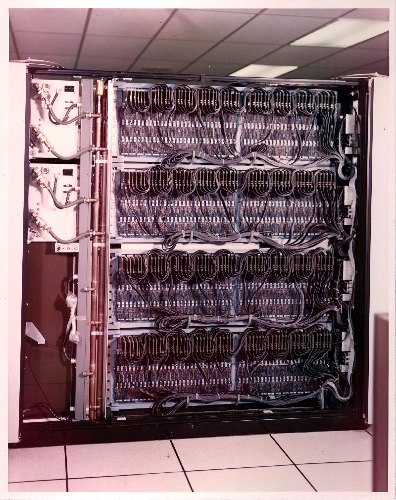 |
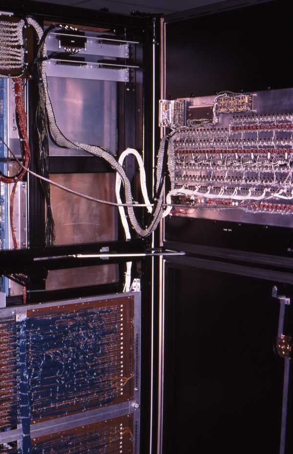
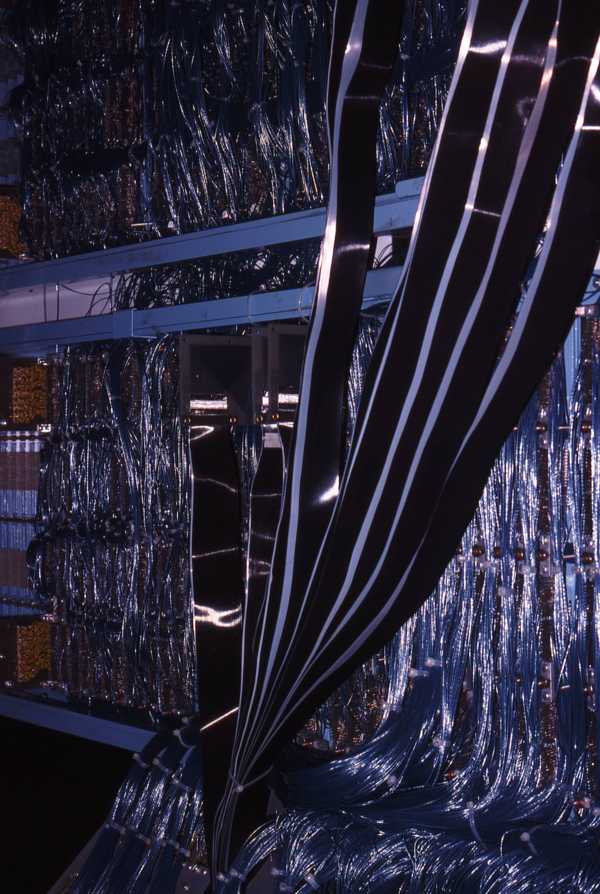
| Processing Element Bay backpanel view. The power supplies were water cooled. The PEPE control console was in another cabinet. It sent control signals over the ribbon cables to each PE. |
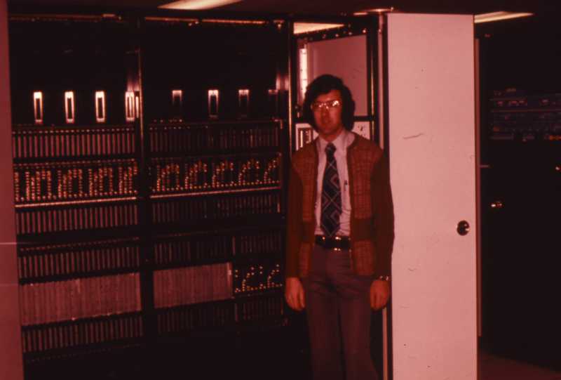
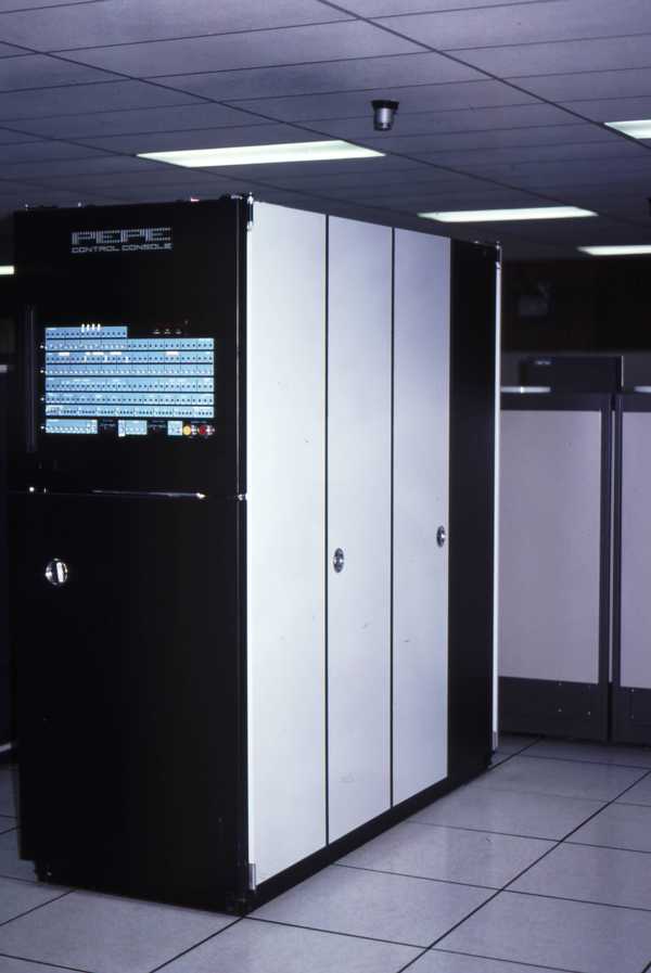 This is the control console. It contained the interface to the CDC-7600 computer used for actual operation and to the B-1700 used for development and testing. |
 Control Console with doors open. |
 Power supply. We had a fork-lift sort of device to help us remove the power supplies for maintenance. It was a switching supply. Cooled by chilled water. |
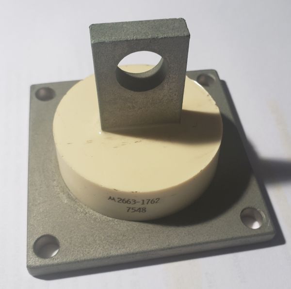 The diodes in the supply were a real weak point. We had alot of failures of those diodes. Motorola part number 2663-1762. Note the date code of the 48th week of 1975. |
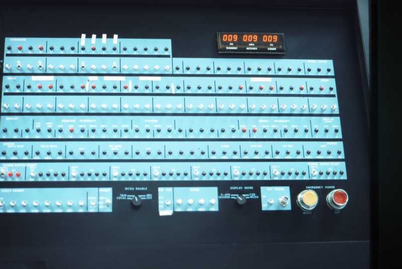 Control Console control panel. The LED display showed how many of each of the three units in each PE were online at any time. Notice the external clock BNC connector. PEPE was completely synchronous and could be operated with a clock speed of 10MHz (100 ns) down to a push button rate |
 This is is the rear of the control panel. |
 This is the backpanel of the Control Console. |
 This is the interface logic. |
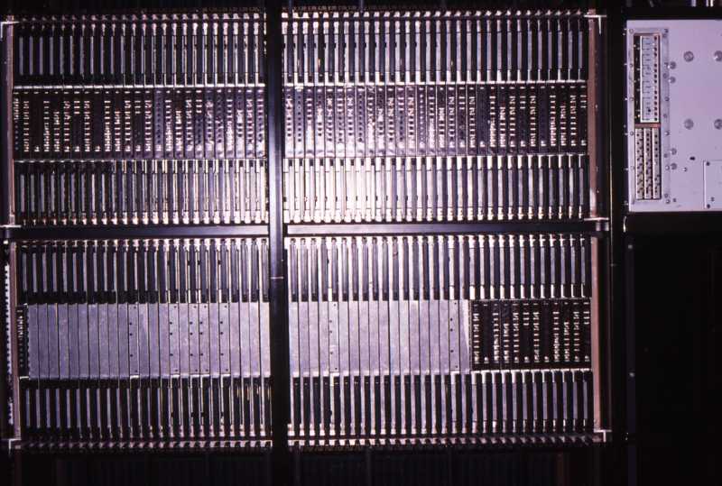 Front of the PE bay. The top row contained 9 PE. It looks like the second row contained 2 PE. The card on the far left was for clock distribution to the row. |
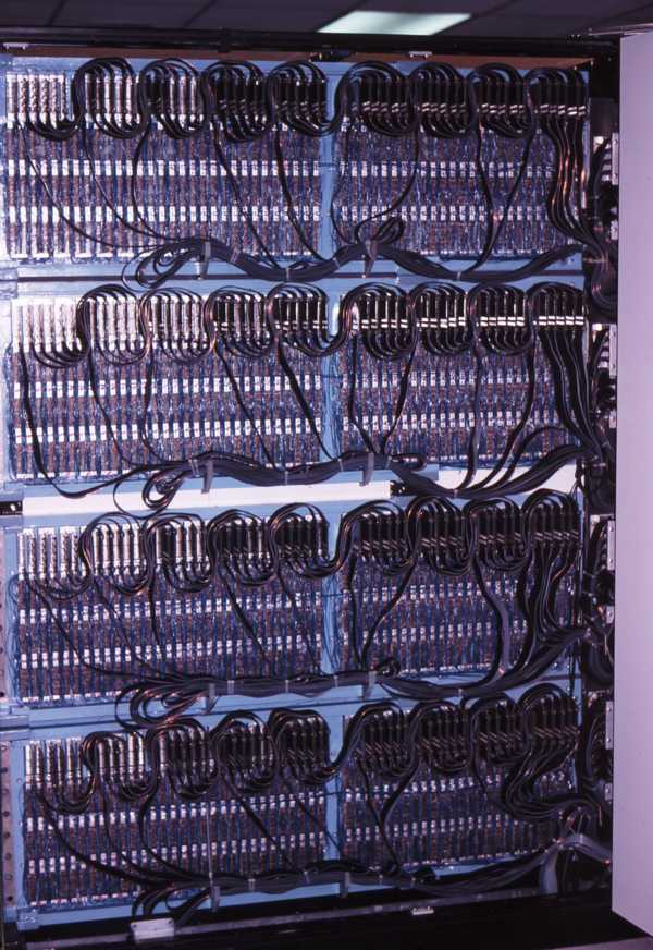 Backpanel of the Processing Element (PE) Bay. Note the pattern of daisy chained cables. These cables distributed control signals from the Control Console to each of the 9 processors in each row for a total of 36 processors per bay. The Control Console could then control up to 8 PE bays for a grand total of 288 processors. IIRC we built 9 Processing Elements plus 2 sets of spares and one PE Bay |
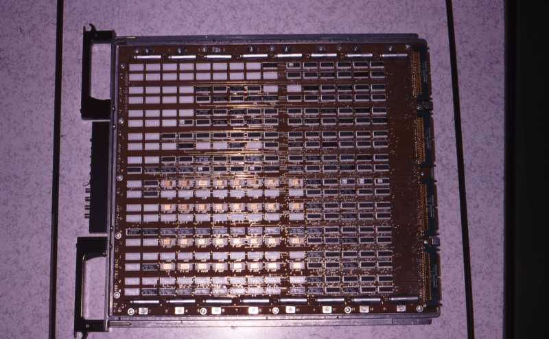 Typical PC board of PEPE. This, I believe, was the Memory Board of a processing element. |
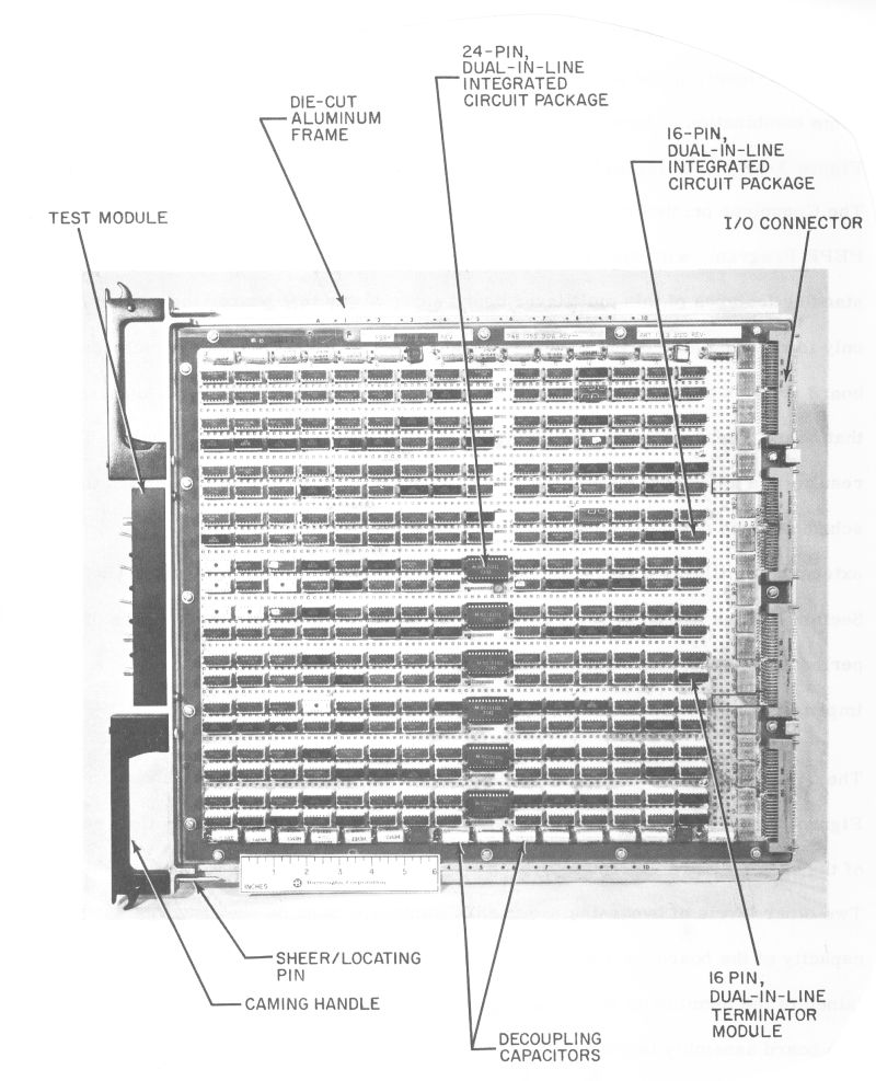 Here is a photo of a typical board showing some of the features. I believe this is the Arithmetic Unit (AU) of a processing element. The 24 pin IC were a 4-bit bit slice Arithmetic and Logic Unit (ALU). It appears there were 6 spare IC locations on the board |
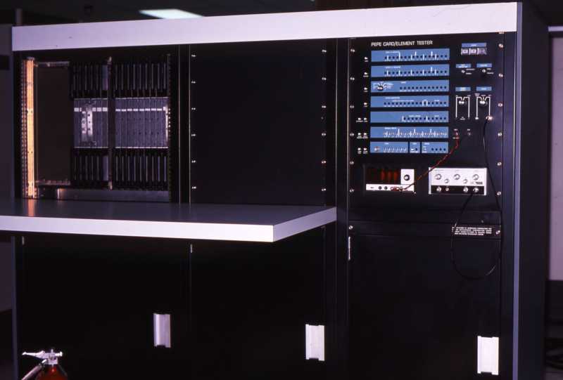 PEPE Card/Element Tester. This box could test any of the boards in PEPE. |
 Burroughs B-1700 Test and Maintanence Control Computer |
 "IT" This is the interface logic which connected PEPE to the B-1700 - the test and maintainence interface. |
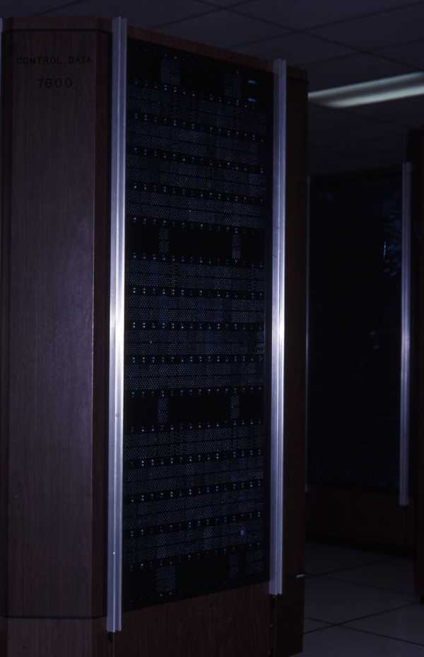 Control Data 7600 - PEPE's main operational interface |
 System Development Corporaton hosted the BMDATC (Ballistic Missile Defense Advanced Technology Center) in Huntsville, AL. |
 |
 |
 PEPE Match Box |
 PEPE T-Shirt As of 2021, I still have this T-Shirt. |
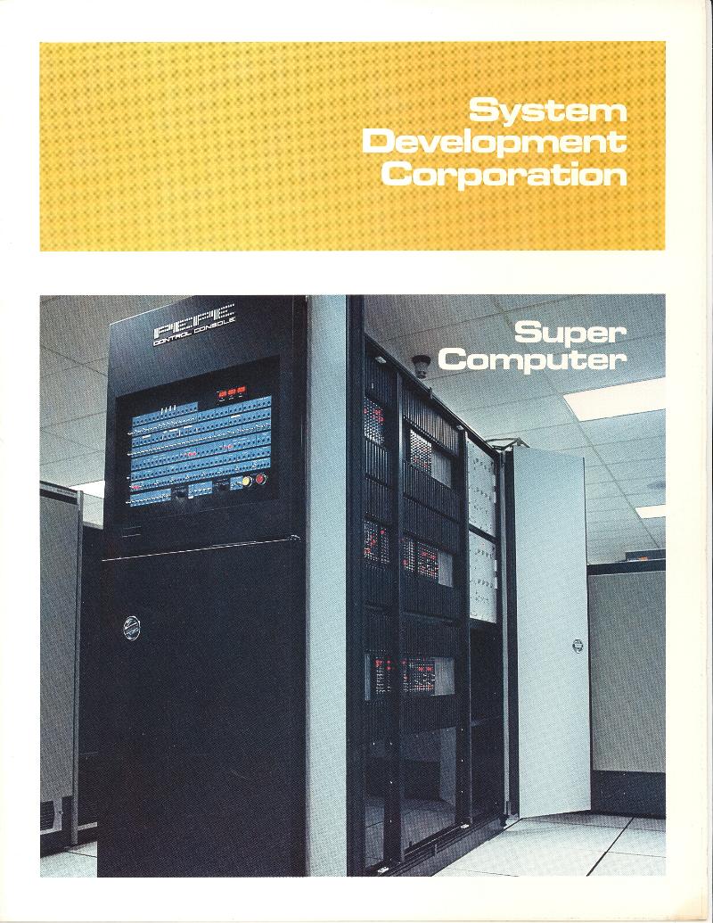 |
| Click on the scan, above, for a pdf of the entire brochure. In it are photos of Bob Sidnam and Benny Sisk, the two people at SDC that we worked with. Also includes photos of Howard Welsh and Jerry Schweitzer (who worked with me at Burroughs). |
 |
 From the July 1977 Burroughs B-Line, an in-house magazine of the Federal and Special Systems Group.
|
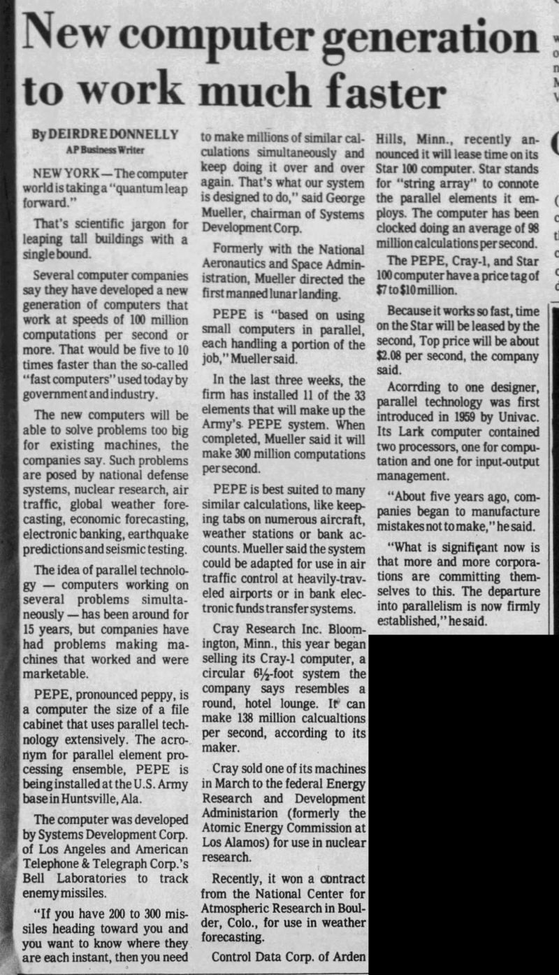 24 Sep 1976 Tucson Citizen
This was an article that went out over the AP wire and it appeared in dozens of newspapers across the country. Didn't mention Burroughs! |
 |
 |
| Date: Wed, 02 Jun 2004 21:32:13 -0400 From: John Sternbergh <john  astrapoint.com> astrapoint.com>Subject: A Voice from the Past Mark: I was searching for information about the Burroughs' PEPE system on the web, and I found your name and email addresses. It was a pleasant surprise. I hope the years since we've seen each other (all 28 of them) have treated you well. Tacie and I now live in Durham, NC, and our daughters live near us. I'm currently employed by Blue Cross and Blue Shield of North Carolina, and I'm enjoying the challenge. Please drop me a line if you're so inclined. It would be nice to hear how you're doing. Regards, John Sternbergh |
| John, Great to hear from you. It certainly has been a long time. The last I remember, you were working for SMS across the street from the old Burroughs plant. I still keep in touch with a few of the old crew; Chuck Yonko, Larry Watson and Jim Dix. Chuck and Larry both live in New York, near Binghampton and Jim still lives in PA. Chuck and Larry work for remnants of IBM which were sold to other companies. All three have been out here and I've seen them at various times over the years. I've written to Carl Semmellhack several times but he has never written back. Paulo MacCormick retired from Burroughs maybe 15 years ago and now lives in Miami, FL. I've been in San Diego since leaving Burroughs in 1978. I worked for five years for National Semiconductor and then had my own company, Silogic Systems for almost 20 years. We did chip design. I got "bought" by one of my clients in 1999 and went to work for them for a few years. Last year, I left there and now I'm either retired or between jobs. About 10 years ago, I made an attempt to find PEPE. I traced it from Huntsville, to Kwajalein Island to Auburn University in Alabama. I finally actually spoke with someone who was involved in the "junking" of PEPE. It was completely gone and he didn't know any more of what became of it. I noticed that searching on the web, I find refrences to PEPE in "History of Computing" and other such sites. I guess we've crossed over the line into being "olde timers". My current time is wasted by genealogy research. I haven't been back to eastern PA since I left. I imagine it has changed a LOT! Mark |
| Alan, I hope this email gets to you and that you are doing well in your home. San Diego will never be the same. I'm putting together a web page about the PEPE computer and I was wondering if you have any photos of GreatValley Labs? Mark |
| Date: Sun, 16 Sep 2007 15:35:20 -0600 From: Alan Whiteman Subject: Re: Burroughs GVL Hi Mark Hum ... I don't think so - much was lost and discarded when I was packing up and leaving in those frantic last few weeks. Alan |
| Date: Wed, 21 Apr 2010 11:51:43 -0700 (PDT) From: Nina Cornell <nina.cornell yahoo.com>Subject: PEPE Read your site on PEPE. Wondered why you never mentioned Bell Labs (Dave Bergland) and later John Cornell, Project Manager at SDC in re the origins of the computer. SDC bid and won the contract to build the 13 element processor as conceived by Bell Labs Whippany. A group from SDC, Santa Monica, Ca. headed by John A. Cornell relocated to Whippany and after a one year transition the group relocated to Huntsville. Nina Cornell |
| Nina, Thanks for your email. In my lowly position on the PEPE project, I didn't have much contact with the important people at SDC. We worked with Benny Sisk and Bob Sidnam. I looked at the final report of Phase I of the program and I see the names: J.A. Cornell, G.J. Hanson, and R.G.Mueller. This document was dated 30 Jun 1973 shortly after Burroughs got involved and I got hired. I would like to learn more about how the project was run during the early phases. We did our design work based on design speciifcations written by Honeywell. If you have a chance to tell me more, I'll add it to the web page. Mark DiVecchio |
| From: Walter Wikiera <wjwikieramsn.com> Date: Sat, 22 Sep 2012 07:33:47 -0400 Hi Mark, This is Walt Wikiera retired. I happened to see your article on PEPE and it brought back good memories. This was one of the better programs in my career at Burroughs and working with you was a pleasure. I presently live in Florida. I retired from Burroughs (Unisys) in 1990. Best of Luck, Walt |
| Walt, Thanks for your email. My web page keeps on attacting people from the old group at Burroughs. Over the years, I've kept in touch with Bill Sullens, Larry Watson, and Chuck Yonko. Two people that I would have liked to have heard from are Carl Semmelhaack and Herb White (my boss). Never heard from them. PEPE was a good project, also one of the best projects that I worked on over the years. Sadly after the 1980's, companies weren't making large computers anymore. I spent most of my career designing ASIC's. Would you like to write up your memories of the PEPE program? I could add that to my web page. Mark |
| From: Walter Wikiera Subject: PEPE remembered Date: Tue, 25 Sep 2012 09:55:03 -0400 Mark, Looking back on the PEPE organization I realized that we had some of the best talent a project could have. I did not remember that Don Faulis was part of that team until I saw him on the organization chart. He is one of my best friends and I have visited him several times in California. No one was a better mechanical engineer than Dick Stotler. Herb White was a meticulous and talented electrical engineer. As for Carl Semmelhaack, he was a brilliant software/system engineer, although if you didn't know him, he didn't come across as impressive. There were others that made the project as successful as it was: yourself, Bert Beckmann, Elmer Duckinfield, Harry Hess and many many others. Mark, it was a very talented team with much experience but it was adding new thinking that made it go. I would be remiss if I didn't add SDC personnel such as Bob Sidman to the PEPE team for it's success. I've worked on other good projects, but none more pleasurable than with the personnel on PEPE team. Walt |
| Date: Thu, 2 May 2013 16:22:02 -0500 Subject: PEPE at Auburn From: Kyle Owen <kylevowen gmail.com>Hi Mark, First of all, I have thoroughly enjoyed your website dedicated to PEPE. That was a very interesting time in computing history for sure, and your website really ties it all together very well. Thanks for the great pictures, too! I see you have mentioned Auburn University as the final resting place of PEPE. I'm currently a to-be senior in computer engineering there, and as a vintage computer collector, I decided to do some digging on the big machine. Sure enough, several of the guys in the department remember PEPE quite fondly. I'll be trying to get in touch with a few of the guys that actually programmed it while it was partially working at the university perhaps over the summer. As you are definitely aware, it was in fact scrapped. All of the 7400-series ICs were desocketed and stuck in drawers, only to (rarely) be used again in some digital electronic labs and such. One of the other remnants is a Processing Element Bay badge stickered to a 19" rack. I'm sure the copper and what not from those power supplies were recycled, and apparently the hydraulic lift used to remove large parts from PEPE is still being used around the department, from what I understood. I figured you may be interested in a picture. It's not much, but maybe it'll help tie up the bottom of your webpage or something. Thanks again, Kyle Owen, W4GNU |
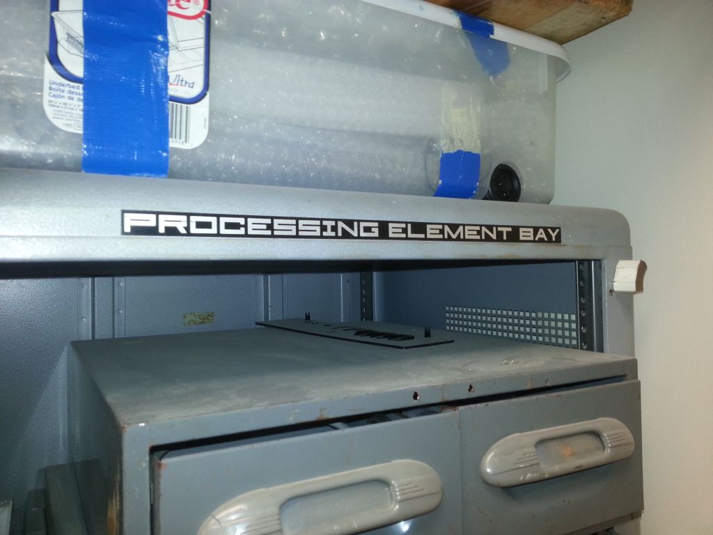 Kyle noted that the rack cabinet to which the badge is attached was not part of PEPE.
|
| Kyle, If you are in Huntsville, you could try to find the old System Developments Corporation office (which I think was bought by Burroughs, which is now Unisys). Bob Sidnam and Benny Sisk were our two main contacts with that company. They would both be in their 70's and certainly retired. Jerry Fowler was one of our techs who stayed with PEPE when it was left in Huntsville and he might still be around somewhere. He would probably be in his 60's. Besides the two main PEPE cabinets, there would have been a card tester cabinet and the B1700. The B1700 had a maintenance interface to PEPE. There was a separate interface from the CDC7600. The CDC7600 was a very large expensive machine. I doubt that it came with PEPE. The B1700 could have been used to do everything that the 7600 did, although through a much slower interface. I've attached a file that shows the interconnection of the cabinets. Good luck, Mark |
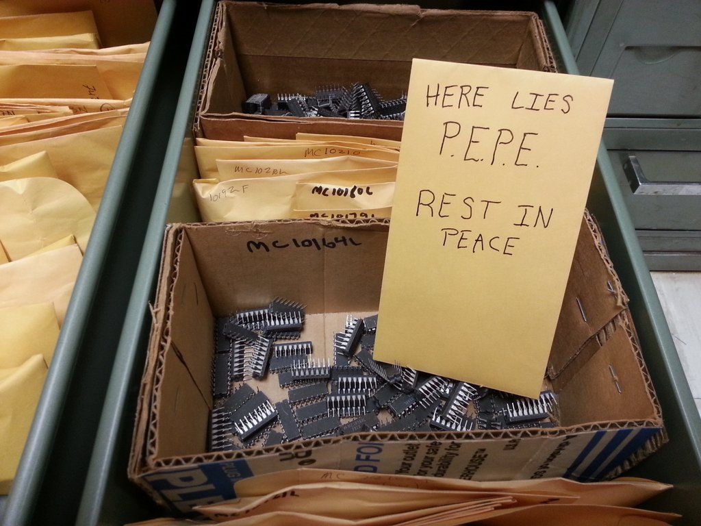
| Mark, Thanks for the added info, Mark! I'm loving all of this research. I've got some more research to do at Auburn, for sure. I'm going to get a dissertation from one doctorate that likely wrote about his experience with PEPE while it was at Auburn. I may see about getting that before I leave for Huntsville. I've updated my album. Feel free to grab the images from the album and rehost them. For posterity's sake, I took a photo of the "RIP" sign on some real MECL. Only the most astute of observers would notice the difference, but you know, it's always the little things. :) Dunstan Hall is fixing to be torn down, so I'm glad I got access to those rooms prior to the demolition. Turns out I also found some old stacks of punch cards filed away in a storage closet. Looks like mostly data, but there may be some more programs back there too. Probably not PEPE-related, though. There were several other machines in Dunstan that required punch cards, of course. 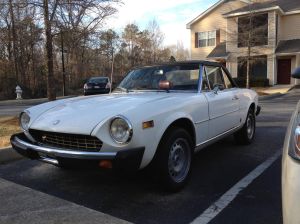 If you give me your address, I could send a few MECL parts your way if you'd be interested. I can only assume that the date codes around 1973 were from PEPE, and likely no later. I did come across a large quantity of parts from 1976, too, but I would say those could not have come out of the original PEPE. Also, on an unrelated note...I checked out more of your website, and you sure do have a stunning MGB! About two years ago, I was dead-set on getting an MGB (I couldn't afford an MGA) but my dad really urged me to consider some Italian engineering instead. I bought a 1976 Fiat 124 Spider and have had a blast driving it, but find myself working on it perhaps more than driving it. Well, not quite, but I'll say I did spend a lot of time fixing the brakes, though it's still pulling hard left when braking. I think I may have a stuck caliper or something on the right, despite all four being "professionally" rebuilt by my shop. The Fiat's bumpers are certainly not as attractive as the early all-chrome stuff, but it's more tolerable than the later MGBs in my opinion. Kyle |
 |
 |
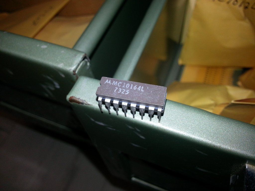
| Kyle, Thanks for the new photos. The MECL chips with a date code of 7325 would be about right. I started at Burroughs in April of 1973 at the start of the PEPE project. We probably had the design ready to buy parts within a year, so parts made in the 25th week of 1973 were a good candidate. I recall that all of the MECL chips were socketed so removing them would have been easy. Its funny that its been so long but I remember exactly the function of the 10164 in the photo (8 to 1 mux) and I probably still remember all of the other chips functions as well. We delivered PEPE in 1976 to Huntsville. It may be possible that SDC ordered more ICs to build up the maintanence spares for the trip to Kwajalein Island. I would like to have a few of the chips. They may be ICs that I actually touched! About your car : I could make a lot of jokes about English vs. Italian engineering but I'll refrain from doing that ...... I have a cousin in Italy who has an original Fiat 500. Talk about small, its about half the size of the newly introduced 500. And NO synchros in any gear! I love my MGB though. I tried to keep it running but the dual carbs were too much for me. I got it professional help a few years ago and now it runs great. Nice old technology - I can actually understand how it works. Your 124 is certainly beautiful. Mark |
| Date: Wed, 6 Nov 2013 12:30:28 -0600 Subject: More PEPE Stuff From: Kyle Owen <kylevowen gmail.com>Hi Mark, Sorry it's taken me so long to get back in touch with you. This past summer didn't turn up anything in Huntsville regarding PEPE, though I was told there may be a guy up there who is still alive that used PEPE in Huntsville and would be willing to chat. I may be back up there this winter and might be able to further investigate. I also tried looking around for the SDC building, but didn't find anything that resembled it. Do you recall where it would've been located, by chance? I did find some more PEPE parts around Auburn, though. I will try to get a package sent your way soon. I think you'll be quite impressed to see what I've found: some sample backplane wiring, as well as some black/white twisted pair as seen connecting the front panel to the rest of the machine. I'll send you some MECL parts and some of the coaxial wirewrap wire for nostalgia's sake. I'll try to have that shipped in the next couple of weeks before exams. Oh, I also did some digging around at the library and found a thesis written on active filters. Turns out this was all done on PEPE during its short running lifetime at Auburn. Apparently it never was quite up to snuff when it was here. I also found what I suspect was the hydraulic lift used for removing and installing the power supplies. I'll send you a picture later; maybe you can verify that. Within the past month or so, I started working with a professor of computer science to restore some old computers of his, including an original PDP-11/20, a PDP-8/E, a few MicroVAXen, etc. I started asking around the EE building to find some photographic history of computing, and sure enough, one professor had some photographs from no earlier than 1981 of the department's computers, including a PDP-11/40 system, the VAX-11/780, some Harris 24-bit mainframe, etc. Unfortunately, I saw no shots of PEPE, as I suppose it may have been trashed by then. I've scanned the pictures in if you'd like to see them: http://imgur.com/a/Kwnn9 I hope you and the MGB are doing well, Kyle |
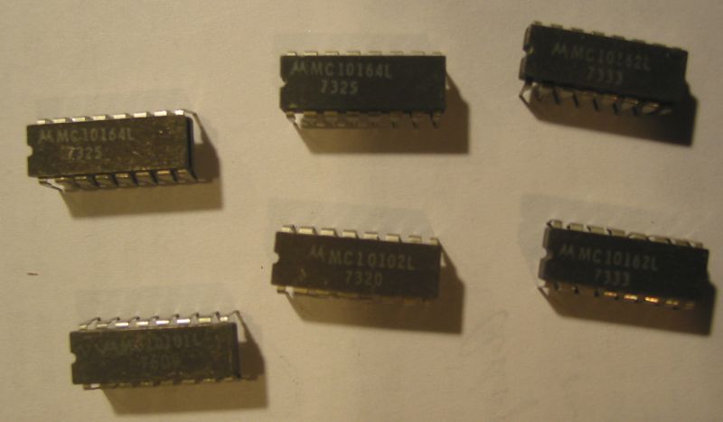 6 MECL 10K chips.
10164 8-line Multiplexer 10162 Binary to 1-8 Decoder (High) 10101 Quad 2–input OR/NOR gate 10102 Quad 2-Input NOR Gate These all have date codes of 1973 which is when we started the design of PEPE. |
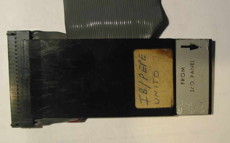 One of many flat cables used to
interconnect PEPE with other computers. In this case, the "IB" was the
Interface Buffer that connected PEPE with its maintainance computer,
the B1700.
|
 A clock distribution cable. Every flip-flop in PEPE was clocked at the same time within a few nanoseconds.
|
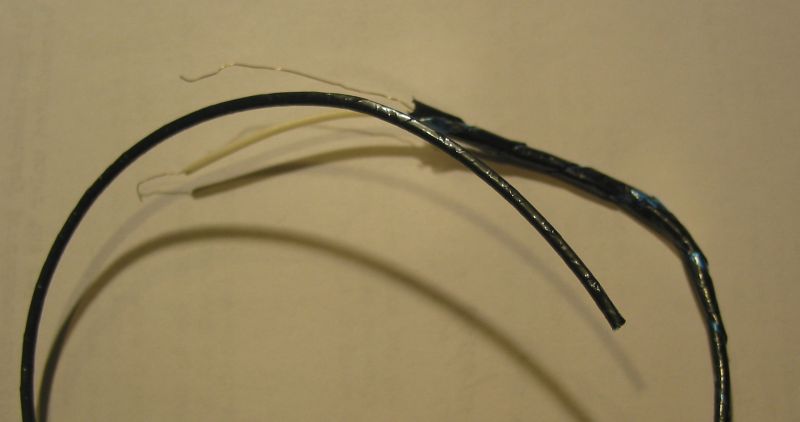
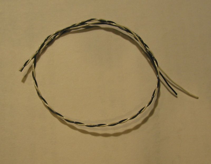 I don't know exactly where this wire might have been used.
|
| From: Jim Petrosky <jmphotog1msn.com> Subject: Great Valley Labs Date: Mon, 23 Feb 2015 10:05:55 -0500 Hi Mark! My name is Jim Petrosky and I too had worked in Great Valley, GVL-3 to be exact. There was a repair depot in the early '70's where we worked on DFSU's. Our "clean rooms" were inflatable clear plastic tents. At sometime in the earlier '70's, we were moved to Downingtown and had a real clean room built. Worked there until I left in 1978 to pursue professional photography which I still do today. I found your PEPE site, http://www.silogic.com/PEPE/PEPE.html , and thought I'd say hi. Also wondering if you may have known some of the supervisors such as Ed Litwinic, Jim Shaughnessy (or maybe O'Shaughnessy, Atwell, Minarcik or Neal Doll. Spellings may not be correct but close enough. I want to say you were in GVL-1. Yes?? James Michael Photography www.jamesmichaelphotography.com |
| Jim, Thanks for your email. When I was on the PEPE Program, I worked in the building lowest down the small hillside. If I recall, the guard house was in front of the middle building and we were in the building on the left. I don't remember the building numbers. I don't recognize any of the names you listed. Dick Stotler might be the only person that I worked with who ended up in Downingtown. I'll add your email to the web page if that is ok with you. Mark |
| That would be GVL-3 where I had worked. GVL-1 was at the top of the hill. Even though we never met back then, I enjoy the throwback of life at a simpler time. Not familiar with Dick Stotler. Thanks for getting back to me. By all means, feel free to add my email. Thanks! Jim |
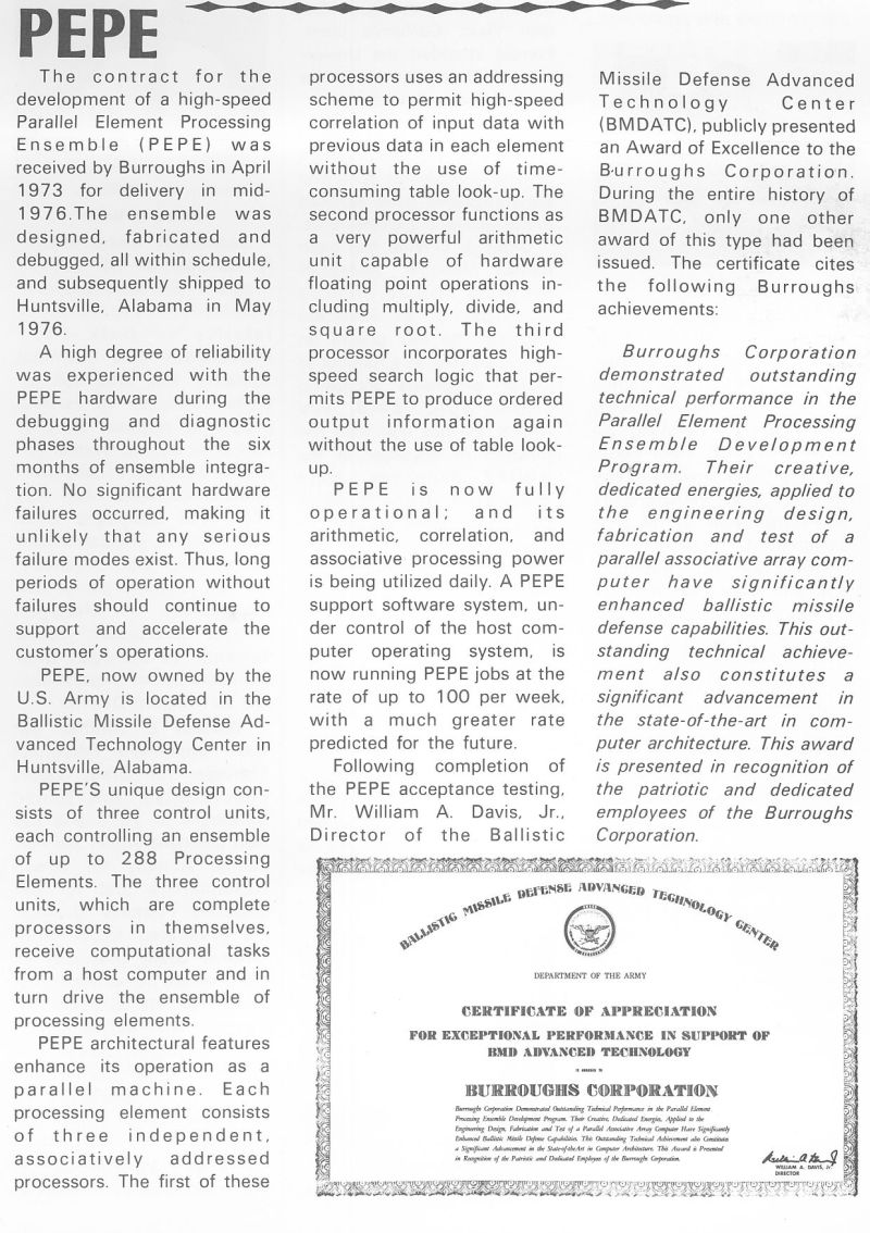
PARALLEL ELEMENT PROCESSING ENSEMBLEAs studies of ballistic missile defense systems progressed, the postulated threats expanded greatly in terms of the number of objects arriving simultaneously and the sophistication of the penetration aids. This increase in threat influenced ABM design and especially increased the estimate of throughput needed for ABM data processors. In response, a new concept of architecture for the ABM data processor was suggested.14 Because a large part of the processing associated with radar tracking and discrimination required that the same set of algorithms be repeatedly applied to each object, parallel elements might carry on the processing. In 1964, research began on a content-addressable memory invented by Lee and Pauli of Bell Laboratories. This memory offered an approach to the needed parallel processing, and a follow-on development program supported by the Advanced Ballistic Missile Defense Agency (ABMDA) led to the Parallel Element Processing Ensemble (PEPE) concept. PEPE was a programmable, special-purpose computing machine that augmented conventional sequential computing in ABM data processing. Processing capacity was largely independent of traffic because an independent parallel element was assigned to each object in track. Each parallel element was, in fact, a small digital computer, with an arithmetic unit and memory. In addition, each contained a special-purpose input unit called a "correlator," which associated radar replies with the appropriate track by simultaneously comparing each radar reply with predicted track positions. Most of the control circuitry was in an ensemble control unit, which was connected in turn to a more conventional "host" sequential digital computer. The host computer stored instructions for the parallel ensemble, sequenced through them, and passed them to the ensemble control unit. The host computer also did the processing that could be most effeciently handled by a sequential computer.15 By the mid-1960s, a study was under way to adapt PEPE to ABM. The intent was to realistically assess feasibility and cost factors. Several studies were launched, primarily in the areas of software development and testing. Hardware Feasibility Using readily available components, a processor with 16 elements was built with integrated circuits and tested with an IBM 360/65 as a host computer. This "IC Model" of PEPE was used in the demonstration tests discussed below. A study which showed the feasibility of using more advanced large-scale integrated circuits in PEPE was completed toward the end of the development project.16 Software Development Since the job to be done by parallel processing elements would be done the same way by a sequential computer, similar programming methods could be used. A parallel version of FORTRAN, P-FOR, became PEPE's basic programming language. P-FOR was supported by a compiler and an assembler to convert programs into machine code. Also, programs could be written for input to the assembler using PAL, the Parallel Assembly Language. The language and software system were available well before any hardware so that programs could be tested by simulation. The P44 precompiler converted each operation on parallel data in a P-FOR program into a DO loop on an array in a standard FORTRAN program. The FORTRAN program could be readily tested on any machine with FORTRAN capability. In addition to P44, which tested P-FOR programs at the source level, the Parallel ABM System Simulation (PASS) simulated operation at the machine level. PASS Tests I to IV, each testing a broader system, were planned. PASS I and II demonstrated PEPE's capability for basic ABM processing and were completed. PASS III and IV were replaced by tests defined by ABMDA, as noted below. Application Studies To identify problems and evaluate the advantages of PEPE, several specific applications were studied:17 • SAFEGUARD. Routines planned for SAFEGUARD as developed in NIKE-X simulations were converted to parallel form in PASS I and 11.18 • VIRADE. As discussed previously under Defense of Strategic Forces, the VIRADE concept added the problems of changing sites to the basic ABM problems.19 • ABMDA defined tests. For a final evaluation of PEPE as part of the Bell Laboratories development program, ABMDA defined two systems: Zero Order Software (ZOS) and Preliminary Hardsite Defense (PHSD). These replaced PASS III and IV. The final PHSD demonstration was against a threat defined by General Research Corporation and transmitted to Bell Laboratories by data link from Santa Barbara, California in interrupted real time. The PEPE system used in this test was the 16-element IC model supplemented by sequential simulation, and it achieved essentially all the test objectives.20 Lessons Learned • The ability of PEPE to carry a large, constantly growing portion of SAFEGUARD data processing was established. The threat level defined for the current SAFEGUARD System did not make PEPE cost effective. Its cost effectiveness would have to be established for a given threat, for a given ABM system, and with the current state of the processor art considered. • The feasibility of increasing system capability by removing processing from a sequential computer and assigning it to a parallel processor was established. • The high level language, P-FOR, was found to be a powerful tool in rapidly programming a complex system. 14. Ballistic Missile Defense, Advanced Development Program, Advanced Data Processing, Vol 1, Bell Laboratories, September 30, 1969. The first of three annual reports; introduces the Parallel Element Processing Ensemble (PEPE) concept and details its architecture and software and initial simulations. 15. IEEE COMP CON '72 Digest: PEPE Computer Architecture, B. A. Crane, M. J. Gilmartin, J. H. Huttenhoff, P. T. Rux and R. R. Shively These papers present a brief overview of the characteristics, PHSD test implementation, and performance of PEPE in a general distribution publication. It was presented as an example of "Innovative Architecture, " the theme of the Conference. 16. Ballistic Missile Defense, Advanced Development Program, Advanced Data Processing. (U), Vol 2, Bell Laboratories, September 30, 1971. (SECRET) Presents an overview of the PEPE IC Model, details and results of PEPE application studies to Ballistic Missile Defense, ZOS, PHSD and Off-loading, and results of hardware implementation studies. 17. Ballistic Missile Defense, Advance Development Program, Advanced Data Processing (U), Vol 2, Bell Laboratories, September 30, 1969. (SECRET) Presents the results of studies of the Application of PEPE to SAFEGUARD, VIRADE, and to Coherent Waveform Processing. 18. Ballistic Missile Defense, Advanced Development Program, Advanced Data Processing, Vol 1, Parts 1 and 2, Bell Laboratories, September 30, 1970. This second annual report presents a detailed description of the Integrated Circuit (IC) PEPE model brassboard hardware and its support software and the PASS II evaluation studies. 19. Ballistic Missile Defense, Advanced Development Program, Advanced Data Processing (U), Vol 2, Bell Laboratories, September 30, 1970. (SECRET) Presents results of GPSS simulation studies of Ballistic Missile Data Processing and design alternatives and a study of the application of PEPE to SPRINT missile guidance. 20. Ballistic Missile Defense, Advanced Development Program, Vol 1, Advanced Data Processing, Bell Laboratories, September 30, 1971. The third annual and final report of PEPE studies at Bell Laboratories. Presents an overview of the PEPE system, hardware and software, and the principal final year studies and demonstrations, ZOS, PHSD, and offloading. Includes an introduction to proposed LSI implementation. |
| Date sent: Thu, 6 Jul 2017 01:51:24 +0000 (UTC) From: herb white <herb2000 yahoo.com>Subject: PEPE post Hi Mark My dad is Herbert White who worked on Illiac IV and PEPE before moving on to the ill fated Burroughs Scientific Processor. My youngest son, Michael, was visiting Mountain View recently and we talked about that time period. Out of curiosity he searched for the project and found your site. He's a software developer for Epic and has that same intellectual curiosity found in the Burroughs team. My dad used to actively be on the internet but now rarely uses it. So I printed everything from your site and mailed it to him. He was very happy and reminisced about those times and the team. It was the hey day of Burroughs and the chance to work on cutting edge projects. It really made him happy to see everything once again. He had grown up in poverty during the great depression and worked his way through city college of NY which led him to Bell Labs, NYU, and then Burroughs. Those years at Burroughs were his favorites. BTW my memories of Illiac IV was as a 10 year old. It was a lot of fun being in Mountain View and attending school with a lot of the navy kids. It also allowed us to travel which in the early seventies was rare. Later before college I worked at Great Valley assembling computers on the commercial side - the factory across the parking lot from the Special Systems group. That's all gone now as you probably know. All in all I learned a lot from the Burroughs experiences. Anyway, thanks for posting all this information and hope all is well with you. Herbert White. |
| Herb, Wow! Great to hear from the son of the Herb White who was my first boss at Burroughs. Over the past 35 years I've thought of your father quite often. My days at Burroughs were also among my best working years. PEPE was a fantastic project for me as my first real computer design job after college. Carl Semmelhaack was another of the engineers that I worked closely with. He was my mentor during that time. I remember when Herb was transferred to the BSP. I've attached a photo of Herb with his boss on the BSP program. Can you ask your father to tell me what he did after the BSP program? Does he know what happened to the PEPE program mananger, Walt Fresch? Mark |
| From: "Jamshed Mulla" <jmullacomcast.net> Subject: PEPE Date sent: Sun, 10 Sep 2017 18:06:08 -0400 Hi Mark: I stumbled on your page about PEPE and was really impressed with all the details you have recorded. I did not work on PEPE itself, but my contact with it came in later years (1976-1978). I worked on my Ph.D. in the late '70s at the University of Michigan where my advisor had a grant from RADC (Rome Air Development Center). I'm not exactly sure how we got connected with SDC and the PEPE project, but in 1976 I started working on my thesis on parallel computing and wanted to look into expanding on the scope of SIMD machines like PEPE. I actually did visit the PEPE installation at the BMDATC in Huntsville with my advisor. In fact, I remember the exact date (Aug 15, 1977) because when we were flying home and connecting flights in Memphis the next day, we heard about Elvis's death! :) My thesis proposed a MIMD version of PEPE where the PE's would have more processing power and actual capability to store parts of the application locally, so that each PE could execute multiple instructions in parallel, thus reducing overall processing time. A lot of the thesis dealt with calculating the expected speed improvements of MIMD over SIMD. As I recall, I also proposed a programming language for such a MIMD machine. A fellow student who was working on his Master's degree built a prototype of the machine using (I believe) 8 Motorola 6800 processor boards. If you are interested, a brief paper on my thesis is on-line here <https://deepblue.lib.umich.edu/bitstream/handle/2027.42/5687/bac5077.0001.001.pdf?sequence=5> . I used the term "associative processing" as I presented the concept as a natural extension of associative memories which were somewhat the rage in the day. :) Regards, Jamshed Mulla |
| Jamshed, Thanks for your email about PEPE. I looked at your paper. I also recall associative memory being a hot topic back then. I don't think it was ever appreciated as being as a really different way to approach computer programming. If its OK with you, may I add your email to the PEPE web page? Mark (My Elvis is dead story: I was still working for Burroughs. We were back in Paoli from Huntsville and working on the next computer. We were meeting the customer (Lincoln Labs at MIT). Our team just met for breakfest before heading to the Labs and one of other members told us of Elvis's death.) |
| Hi Mark: Absolutely! No problem with adding my e-mail to the web page. I am also going to forward your link to my college colleague who worked on the physical implementation of the associate processor. His name is Dave McCubbrey. He has worked on parallel processing systems, mainly for image recognition, for most of his career. He is now president of a company called Pixel Machines. - Jamshed |
| Date sent: Mon, 1 Oct 2018 08:22:10 +0000 (UTC) From: Bob Davis <robert.l.davis att.net>Subject: Parallel Processing Mark, Was wasting time looking on the internet and stumbled on to your PEPE post. Carl S. and I came to Burroughs about the same time (1967) and worked on ILLIAC IV together. A photo of one quadrant (64 processing units) is attached. One key was the barrel switch for single clock time shifts of any length for things like alignment of mantissas before a floating point add. Here's one patent that came from that. After our team's design and building of a couple of breadboard units, I moved back to the main building in Paoli. Next, worked on the D-Machine and its use in the corporate disk pack controller and on an aerospace multiprocessor for AFRL at Wright Patt. Those machines were modular from 8 bits to 64 bits in 8-bit increments. It took a bit of fiddling to get a barrel switch with all its connections down to something that was modular and could be extended in word-length while maintaining the internal design for each 8-bt slice. Since we implemented the slice using TI's LSI array, pin count really was important. Carl helped me with this and even came up with a scheme to use a barrel switch for routing in ILLIAC IV (never used) that could route data simultaneously between any distance of processors, and not just the +/- 1 and +/- 8 it was designed for. Since Carl's kids and mine were close in age, we got together with them often socially. A fun family. Carl was a very inventive guy and a great person to work with for the 9 years I was at Burroughs. I left in 76 and moved to Dallas to work on speaker & speech recognition at TI, telecom at a Honeywell-Ericsson joint venture, then 23 years at E-Systems (now Raytheon) doing imagery and multi-int reconnaissance and surveillance ground stations for the government. Have been retired since 2008, mostly working on genealogy, lately concentrating on DNA testing. I enjoyed looking through your post. Bob |
 |
| Bob, I learned more working with him for a couple of years on PEPE than I learned in 4 years of college. I see that Dick Stokes was listed as one of the inventors on that patent. I worked with him on PEPE and later (for a short time) on the mail sorters being developed in Downington. When I left Burroughs in 1978, he (along with my boss on PEPE, Herb White) was working on the BSP project. I left Burroughs before the merger with Univac. Mark |
| Mark, Here is obit for Dick Stokes from 2012. https://www.legacy.com/obituaries/delcotimes/obituary.aspx?n=richard-a-stokes&pid=157661625. Hope this helps. Glad you had a good trip. We still have friends from Burroughs days that were from India, but don't know if you ever ran into them since he ([Kitur] Shankar} worked in Advanced Development which is where I was up on Central Ave except for the years I was on Illiac IV down in the middle of the three old buildings in GVL. Bob |
| Bob, I had not heard of Dick Stokes passing. Thanks for that information. Did you anybody else from ILLIAC IV who worked on PEPE? Mark |
 Date sent: Mon, 7 Sep 2020 22:00:12 +0000 (UTC) Date sent: Mon, 7 Sep 2020 22:00:12 +0000 (UTC)From: Bob Davis <robert.l.davis att.net>Subject: Carl Semmelhaack Mark, I know that you worked with Carl Semmelhaack on PEPE and wanted to make sure you had gotten this word that somehow I missed. Since we moved to Dallas in 1976, we lost close contact with Carl and Ellen during my 10 years at Paoli and GVL We did however trade Chrismas letters until Ellen's death in 2016. For some reason I goggled Carl today and was surprised to find that he had died last Arpil, 2019. While they were about 5-7 years older than us, our kids (4 for each of us) were roughly the same ages, so we spent many happy hours with them as a couple and as families. They lived in Lenape while we were still in PA. I am disappointed not to have visited with Carl in the last couple of years after Ellen died. We had talked about going to FL several times, but just never seemed to make it. They were both dear, close friends and are / will be sorely missed. https://www.dignitymemorial.com/obituaries/largo-fl/carl-semmelhaack-8248871 Don't know how many others in the Advanced Development group you might have known since I think you were in GVL. I'll list what I know of some of them as I remember them. Earl Reigel - Retired and living in Downingtown Kitur Shakar - Retired and living in Houston Si Gluck - (worked on EDVAC in late 1940s) died Feb 2019 George Cowan - retired, living in Maryland Jim Bondi - retired, living in Dallas Others I've lost track of - George Barnes, Dick Stokes (think he died in 2012), Al Long, Dave Fischer, Dick Faber, Eric Bittmann, Dave McGonagle, Al Sankin. Many others, but the names aren't coming and probably should. I was up there several years ago and noticed that the Paoli building on Central Ave. was gone and replaced by a big spread of condos. Anyway, Carl's passing is probably old news to you, but a bit of shock to me. I expected Carl to outlive us all. Bob Davis |
 Carl Semmelhaak 1935-2019 |
| Bob, Thank you for letting me know about Carl. I had not heard. We are all getting up there in age and we are all in for the count. Carl made a big impression on me but we never managed to keep up contact after I left Burroughs. Looking back at how little I knew when I interviewed with him in 1973, I'm still amazed that Burroughs hired me. Fortunately, he filled my head with knowledge while I was there. I've put your email on my PEPE web page. Let me know if you would rather I not. Mark |
| From: "Wright, Mark W" <mark.w.wrightlmco.com> Subject: GVL Memories Date sent: Wed, 13 May 2020 19:30:20 +0000 Hi Mark, I vaguely remember you. I was hired as a high school intern in April 73 as well. Was hired for TRITAC which folded by the end of 73 and then I was working on PEPE and a Lincoln Labs job and AABNCP that I believe Carl worked on as well. I was in the group they called Design Assistance. I did the trace routing for the PC boards and produced the wiring card decks for the Gardener-Denver machines that did the wiring of the wirewrap boards. Your pic of the PEPE backplane brought back memories. The printed circuit trace routing was done on the B6700 mainframe in Bldg 1. The program would run for days to come up with a solution. Punch card inputs and Gerber magnetic tape outputs. We read in the tape in the plotter lab in Bldg 3 and created 'artwork' on glass etching for each layer of the board which we'd send to the board manufacturer. A lot of those names bring back memories - Dick Stotler, Walt Fresch, Elmer, Harry Hess, Bob McQ, of course Carl was a great friend and mentor. That was a first class team. Can't remember the name of the program that same team went to after PEPE wound down. We started ARTSII in '75 which wound up here at Valley Forge Lockheed and only shut down in 2019 when Jim Bacon and Wes Herrick retired. Thank you for creating the page that keeps this stuff alive. Good times. I'm still working at Lockheed in Valley Forge, 41 years into it. Still got credit for my service all the way back to '73. Burroughs>SDC>Unisys>Paramax>Unisys>Loral>Lockheed - and through all that I had one office change. take care, Mark W. Wright |
| Mark, Thanks for your email. I'm sorry that I don't remember you but I remember the "DA" group really well. After I finished my design work using drafting pencils and plastic templates on C size drafting paper, those designs were magically transformed into real PC boards by DA. I have strong recollections of the main guy we worked with in DA but for the life of me, I can't remember his name. After PEPE, some of the group moved to the BSP (Burroughs Scientific Processor) and some to a Lincoln Labs project called the IB/DP (Input Buffer/Digital Processor). That was a computer designed to process phased array radar signals. I left B before that project was finished. I'll never forget that we were at a meeting at Lincoln Labs in MA when we heard that Elvis died. I've not heard from any of the guys you mention in your email. I've tried several times to get a hold of Carl with no luck. I dated Harry Hess' daughter for a few months. If you don't mind, I'd like to use your email on my web page. Mark |
| No problem using the
e-mail. The DA group was headed up by Dick Conger, I worked
with Charlie Martino and Vince Avarese. Sandy Gundel was in
charge of the data entry. The BSP job was something,
endless overtime and then all of a sudden - stop work, think that was
in 1980. I worked 108 hours in a week on that. Unfortunately, many
of the people we worked with are no longer with us. I still
have some punch cards, coding sheets and green bar printouts as I moved
into writing software back in the 70's. take care, Mark |
| From: russmcbride73gmail.com Subject: PEPE site Date sent: Fri, 5 Jun 2020 12:43:41 -0400 Mark, I saw your PEPE site. Quite a nostalgia journey. I started at GVL right out of college in 1977 working with Elmer Duckenfield in the mechanical group. Many of the names mentioned on the site are familiar. I worked on Lincoln Labs and the E4-B programs. The power supply picture brought back some memories on the Lincoln Labs supply. I remember taking copper pipe home one weekend and fabricating the water manifolds for the 4 supplies. That would probably be a no-no in the modern world. I was part of a layoff in Jan 1979 and ended up working at Burroughs Bldg 8 in Downingtown. Russ McBride |
| Russ, I worked on the Lincoln Labs IB/DP program right before I left Burroughs. I don't remember you but we must have known each other. I left B in April of 78. I've attached a couple of files about Elmer that I found a few years ago. And four photos from my going away lunch. You might recognize a few people. Those power supplies were really something. B had to build a mini fork lift to get them into the rack. Glad you enjoyed the web page. May I add your email to it? Do you have any photos or documents about the Lincoln Labs IB/DP project that I might post? Mark (Mark's note: I've learned that Elmer passed away a few years ago.) |
| Mark, I ran into Deepak Mithani in Princeton many years ago when he was working for Advanced Micro Devices. I was working for a sales rep company and were the Philly area reps for AMD. You can certainly add me to the web page. Unfortunately, no pictures. Russ |
| From: John Schott <johnschottzzgmail.com> Date sent: Thu, 15 Apr 2021 16:17:22 -0400 Subject: GVL: Funny - I never heard of PEPE I worked some time on Illiac at GVL and never heard of PEPE - but some of the names did ring a bell. Mainly I worked on one of the boards by hand to ensure that the physical path delay of all bits were equal - and I did modify the HE factors of the miserable master control down at one end. I still drive past on Central Avenue where there is an old folks home. Of interest, I managed to alert some folks so that the 1952 cache of momenta in the corner stone was archived at Chester County. About the only GVL face I see is Rick Rudolph, who was the artist of layout of the 14 layer PC boards which were about 39" on a side. Aternate layers were isolation - ground and voltages. Once of the things I remember was what I called the Brain Trust - the people who were so smart that I could not think Mr. Einstein was smarter. George Barnes was my favorate. I have my name on only one patent together with him and Jim Bacon. Bruce Miller is still Mister Deflection when it came to CRT deflection systems. Since you all were more involved with SDC, my big memory is when I got sent there to due to the fact that the Buroughs computer we had sent there caught fire - and in the wooden part of their site in Santa Monica. Overall, I ended up interacting with a lot of the Burroughs locations - from Detroit, to Blue Bell (post merger), several California Burroughs (and SDC) facilities and Mitre. Someone said to me that "You are the Location's Utility Infielder - they don't know just what to do with you until they need someone to fill in a spot. |
| From: Nigel Williams <nwretrocomputingtasmania.com> Date sent: Sun, 6 Jun 2021 16:38:10 +1000 Subject: Illiac IV and Burroughs B6700 Greetings everyone, Please excuse this unsolicited email, I took the liberty of scraping your email address from Mark DiVecchio's informative webpage about the Burroughs PEPE project. For a while now Paul Kimpel and I (and various others) have been attempting to locate documents and related ephemera about the Burroughs B6700 and the Illiac IV. Aside from preserving the history of these machines we would hope we can one day collect enough details to develop an emulator for these machines. So far we have had the least success for the Illiac IV, the only new manual we have found is the CFD manual that Bob Rogallo kindly provided. I have contacted several people who were involved with the Illiac IV and NASA Ames where Illiac IV spent its final days, but very little new information has been found. We do have various early project reports that can be found online, and write ups of Illiac IV experiences (the CERN document is particularly enlightening as it covers the user-experience) but no software or operational manuals have been uncovered. We have had some success with the Burroughs B6700; as of now we have a partial MCP software distribution but unfortunately it is missing several critical pieces that make it unusable as a basis for an emulator. We have a reasonable collection of manuals but there are still many gaps to be filled. Unisys was the source of the partial MCP distribution however that was all they had in their corporate archives. If anyone has any material related to these machines we would be glad to know of it and would be willing to provide assistance in whatever way we can to get the material digitised or otherwise preserved. Thanks, nigel. www.retroComputingTasmania.com |
| From: Jim Petrosky <jmphotog1msn.com> Subject: Illiac Date sent: Sun, 6 Jun 2021 13:05:43 +0000 Hi Mark! I just received an email from Nigel Williams ISO of any info on the Illiac and other early computers built by Burroughs. Although I had no connection to the building or development of these computers. I was hired in 1970 by Burroughs in GVL3 and trained in the repair Depot for the DFSU's, fresh out of high school. Ed Litwinec(spelling?) was in charge a the time. Jim Shaughnessy came later. Did you know either one? I also worked with Larry Minarcik(my age) whose dad had an office in Paoli. I do remember a small sign by the door of one of the empty rooms for Illiac. Apparently, it had already been moved when I started working there. This repair depot took over the space vacated by Illiac. Four small transparent inflatable tents were used as "clean rooms" to repair the DFSU's before a "real" cleanroom was built in one of the buildings on Boot Road. I believe it was building 9 if my memory serves me well. Nigel's email stirred some wonderful, distant memories of my early days. Jus t thought I would share them with you and see if you knew any of the aforementioned. Not sure how Nigel tracked me down. He must have done some serious digging. I am glad he got in touch, even though I could not contribute any info on the matter. Thanks for listening! Jim Petrosky |
| From: John Schott <johnschottzzgmail.com> Date sent: Sun, 6 Jun 2021 17:13:05 -0400 Subject: Re: Illiac IV and Burroughs B6700 To: Nigel Williams <nw retrocomputingtasmania.com>Thanks for the update. I was amazed when I heard of the PEPE machine as I worked on the original GVL machine and was there when the PEPE work was done -- and I never heard about it. (PEPE was an IC based while the earlier version were merely semiconductors. I worked at GVL from 1960 and on for many years. I started in the Circuits area and later System Engineriing. I was on the original Illiac for a while. The control panel version 2 was my real memorial. I did the local and wiring timing (every wire on the panel had to timeout the same as other similar signals (bit x vs. bitu)). The machine was not ICs - so the neat IC array was nowhere to be seen. As to the 6700, I had some interaction with California folks - including being allowed to touch the first two which had a stability problem - GVLs 7700 was rated by them as over engineered ($$$) because of our approach. I helped our division liazon expert to the point that Pasadena assumed that Paoli had a secret expert on the 6700 (we did have a demo site). Since he had suggested several "cheaper solutions", they even suggested that this "expert" should be sent to England where the Barcles Bank 6600 was "too slow". They wanted me to go there as a "fix-all". I pointed that my eight wire speed fix was possible by reading the 6600 "logics" documentation, not by understanding the 6600. (Interestingly, industry wide, West Coast documentation was in the form of "equations" while the east coast people used "physical hardware circuits". \) (I did know more about the 3500 family so I helped the east coast "Tredeffrin" friends do a similar action when the west coast folks wanted to do the upgrades to the 3500 (3700 to 4000 series). I spent a lot of time working on proposals, mostly to the government (USA and other). As a result, I have copies of a number of proposals and manuals on mostly military, post office, international jobs - some of which we got and some not. I don't know if there is a home for them - or the trash pit. I can say that my years at GVL were interesting as someone said "you are a utility infielder" - never to make the hall of fame but .... |
| From: Bob Davis <robert.l.davisatt.net> To: Nigel Williams <nw retrocomputingtasmania.com>Sent: Sunday, June 6, 2021, 03:50:54 AM CDT Subject: Re: Illiac IV and Burroughs B6700 Here is an IEEE paper on the Processing Element. Should be available thru IEEE. "The ILLIAC IV Processing Element," IEEE Trans. on Computers, Sep 1969. There was a list of people at the end, but can't put my hands on the paper right now. There was also a paper on the system by I think George Barnes, Dick Stokes, Dan Slotnick, others? about the same time. Think it is listed in the references in my paper. If you have that, I would check the list. Oh, here is the paper I was referring to. Barnes, George; Brown, Richard; Kato, Maso; Kuck, David; Slotnick, Daniel; Stokes, Richard (August 1968). "The ILLIAC IV Computer" (PDF). IEEE Transactions on Computers. C.17 (8): 746–757. Here are a few people that were involved early on, most of whom have died or are close to it. There were lots of others, but don't remember them off-hand From Burroughs: George Barnes Al Sankin Richard Stokes, deceased Carl Semmelhaack, deceased in FL a couple of years ago Al Long Earl Reigel (lives in Downingtown) Eric Bittman (thin film memories) (Has owned Orchid florist in Exton for years) From TI: Dick (Ulbe) Faber who came to work at Burroughs & GE, deceased several years ago in Honeybrook, PA From U of IL: Dave Kuch Dan Slotnick, deceased I believe Kenji Naemura, back in Japan Maso Kato Sorry I can't remember more. Seems I've run across a couple of old memos that listed lots of people, but have no idea where to find them now. There is a wikipedia article that is pretty extended and accurate. There were a lot of technologies being pushed all at once, and regrettably some things didn't work out - e.g., the thin film memories, multi-layer ceramic substrates for the hybrid packaging in the PE, multi-layer circuit boards in the PE, etc. Even clock distribution had to be done with equal-length coax from its distribution in the CU and even into the PE backplane to maintain Illiac IV's synchronousness to try to get down to the 40 ns clock speed. That's about all I remember for now. Bob |
| From: doug faust <blueberrydouggmail.com> Date sent: Thu, 2 Mar 2023 18:40:11 -0600 Subject: Hi Mark from Doug Faust PEPE Do you still get your email here? Doug Faust Still here in Huntsville |
| Doug, Tell me about PEPE and how you supported her after we all left. Do you remember when PEPE moved from Hunstville? Mark |
| From: doug faust <blueberrydoug@gmail.com> Date sent: Thu, 2 Mar 2023 19:09:17 -0600 Subject: Re: Hi Mark from Doug Faust PEPE I did not go too far. After SDC I to went to Boeing. Got laid off in 1993 from Space Station. Made my way to a job at NASA working with a building automation system. |
| Doug, A couple other guys stayed in Huntsville if I remember correctly. Jerry Schweitzer and another person whose name I can't remember. After PEPE, I worked on a project for Lincoln Labs for a radar processor computer. I was not having fun any more and I left in March of 78 for California. Still spent the rest of my career doing logic design work but the size of the computer kept getting smaller and smaller. Mark |
| Ah, I remember, it was Terry Gore. Mark |
| From: doug faust <blueberrydoug@gmail.com> Date sent: Thu, 2 Mar 2023 20:23:39 -0600 Subject: Re: Hi Mark from Doug Faust PEPE The way I remember it. I went back to PA in the beginning of 1977, working on the Burroughs Scientific Processor. Water cooled monstrosity. I went back to SDC later that year. We packed up PEPE and took it out to McDonald Douglas in Huntington Beach CA and got it running again. About 9 months TDY. We never made it to Kwajalein. Later they shipped it back to SDC. I was never the same. I think we sent it to Auburn. Me and that B1700 were good friends. Doug |
email : markd@silogic.com